- 您現(xiàn)在的位置:買賣IC網(wǎng) > PDF目錄373957 > AD9040APCB (Analog Devices, Inc.) 10-Bit 40 MSPS A/D Converter PDF資料下載
參數(shù)資料
| 型號: | AD9040APCB |
| 廠商: | Analog Devices, Inc. |
| 英文描述: | 10-Bit 40 MSPS A/D Converter |
| 中文描述: | 10位40 MSPS的A / D轉(zhuǎn)換 |
| 文件頁數(shù): | 5/12頁 |
| 文件大?。?/td> | 192K |
| 代理商: | AD9040APCB |
AD9040A
REV. B
–5–
DEFINITIONS OF SPECIFICATIONS
Analog Bandwidth
The analog input frequency at which the spectral power of the
fundamental frequency (as determined by FFT analysis) is
reduced by 3 dB.
Aperture Delay
The delay between the rising edge of the ENCODE command
and the instant at which the analog input is sampled.
Aperture Uncertainty (Jitter)
The sample-to-sample variation in aperture delay.
Differential Gain
The percentage of amplitude change of a small high frequency
sine wave (3.58 MHz) superimposed on a low frequency signal
(15.734 kHz).
Differential Nonlinearity
The deviation of any code from an ideal 1 LSB step.
Differential Phase
The phase change of a small high frequency sine wave (3.58 MHz)
superimposed on a low frequency signal (15.734 kHz).
Harmonic Distortion
The rms value of the fundamental divided by the rms value of
the harmonic.
Integral Nonlinearity
The deviation of the transfer function from a reference line
measured in fractions of 1 LSB using a “best straight line” de-
termined by a least square curve fit.
Minimum Conversion Rate
The encode rate at which the SNR of the lowest analog signal
frequency tested drops by no more than 3 dB below the guaran-
teed limit.
Maximum Conversion Rate
The encode rate at which parametric testing is performed.
Output Propagation Delay
The delay between the 50% point of the falling edge of the
ENCODE command and the 1 V/4 V points of output data.
Overvoltage Recovery Time
The amount of time required for the converter to recover to
10-bit accuracy after an analog input signal 150% of full scale is
reduced to the full-scale range of the converter.
Power Supply Rejection Ratio (PSRR)
The ratio of a change in input offset voltage to a change in
power supply voltage.
Signal-to-Noise Ratio (SNR)
The ratio of the rms signal amplitude to the rms value of
“noise,” which is defined as the sum of all other spectral com-
ponents, including harmonics but excluding dc, with an analog
input signal 1 dB below full scale.
Signal-to-Noise Ratio (Without Harmonics)
The ratio of the rms signal amplitude to the rms value of
“noise,” which is defined as the sum of all other spectral com-
ponents, excluding the first eight harmonics and dc, with an
analog input signal 1 dB below full scale.
Transient Response
The time required for the converter to achieve 10-bit accuracy
when a step function is applied to the analog input.
Two-Tone Intermodulation Distortion (IMD) Rejection
The ratio of the power of either of two input signals to the
power of the strongest third-order IMD signal.
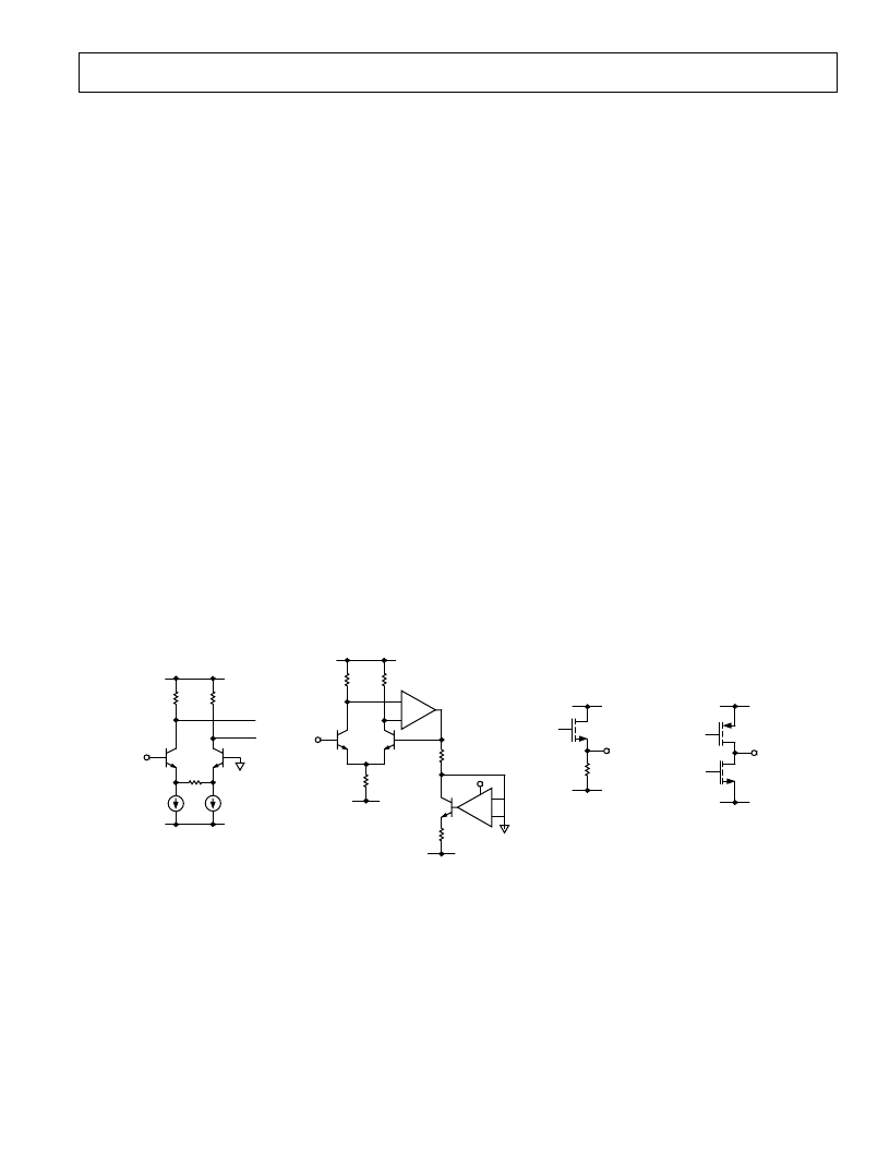
V
CC
V
SS
A
IN
2k
V
1k
V
1mA
1mA
1k
V
ANALOG INPUT
V
CC
V
REF
GND
6.8k
V
R
L
2.5k
V
V
SS
BP
REF
REFERENCE CIRCUIT
V
CC
V
OUT
R
L
GND
BANDGAP OUTPUT
V
CC
GND
D0-9
CMOS OUTPUT
1k
V
1k
V
Figure 2. Equivalent Circuits
相關(guān)PDF資料 |
PDF描述 |
|---|---|
| AD9042DPCB | 12-Bit, 41 MSPS Monolithic A/D Converter |
| AD9042D | 12-Bit, 41 MSPS Monolithic A/D Converter |
| AD9042ST | 12-Bit, 41 MSPS Monolithic A/D Converter |
| AD9042STPCB | 12-Bit, 41 MSPS Monolithic A/D Converter |
| AD9042AD | 12-Bit, 41 MSPS Monolithic A/D Converter |
相關(guān)代理商/技術(shù)參數(shù) |
參數(shù)描述 |
|---|---|
| AD9040APWB | 制造商:AD 制造商全稱:Analog Devices 功能描述:10-Bit 40 MSPS A/D Converter |
| AD9040JN | 制造商:未知廠家 制造商全稱:未知廠家 功能描述:Analog-to-Digital Converter, 10-Bit |
| AD9040JRP | 制造商:Rochester Electronics LLC 功能描述:- Bulk 制造商:Analog Devices 功能描述: |
| AD9042 | 制造商:AD 制造商全稱:Analog Devices 功能描述:12-Bit, 41 MSPS Monolithic A/D Converter |
| AD9042AD | 制造商:AD 制造商全稱:Analog Devices 功能描述:12-Bit, 41 MSPS Monolithic A/D Converter |
發(fā)布緊急采購,3分鐘左右您將得到回復(fù)。