- 您現(xiàn)在的位置:買賣IC網(wǎng) > PDF目錄352486 > AD8138AR-REEL7 (ANALOG DEVICES INC) Low Distortion Differential ADC Driver PDF資料下載
參數(shù)資料
| 型號: | AD8138AR-REEL7 |
| 廠商: | ANALOG DEVICES INC |
| 元件分類: | 通用總線功能 |
| 英文描述: | Low Distortion Differential ADC Driver |
| 中文描述: | LINE DRIVER, PDSO8 |
| 封裝: | MS-012AA, SOIC-8 |
| 文件頁數(shù): | 3/14頁 |
| 文件大小: | 231K |
| 代理商: | AD8138AR-REEL7 |
AD8138
–11–
REV. A
BALANCED TRANSFORMER DRIVER
Transformers are among the oldest devices that have been used
to perform a single-ended-to-differential conversion (and vice
versa). Transformers also can perform the additional functions
of galvanic isolation, step-up or step-down of voltages and im-
pedance transformation. For these reasons, transformers will
always find uses in certain applications.
However, when driving a transformer single-endedly and then
looking at its output, there is a fundamental imbalance due to
the parasitics inherent in the transformer. The primary (or
driven) side of the transformer has one side at dc potential (usu-
ally ground), while the other side is driven. This can cause prob-
lems in systems that require good balance of the transformer’s
differential output signals.
If the interwinding capacitance (CSTRAY) is assumed to be uni-
formly distributed, a signal from the driving source will couple
to the secondary output terminal that is closest to the primary’s
driven side. On the other hand, no signal will be coupled to the
opposite terminal of the secondary, because its nearest primary
terminal is not driven. (See Figure 37.) The exact amount of
this imbalance will depend on the particular parasitics of the
transformer, but will mostly be a problem at higher frequencies.
The balance of a differential circuit can be measured by con-
necting an equal-valued resistive voltage divider across the dif-
ferential outputs and then measuring the center point of the
circuit with respect ground. Since the two differential outputs
are supposed to be of equal amplitude, but 180 degrees opposite
phase, there should be no signal present for perfectly balanced
outputs.
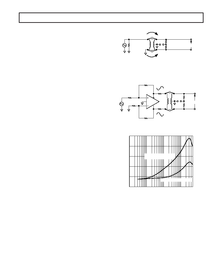
The circuit in Figure 37 shows a Minicircuits T1-6T trans-
former connected with its primary driven single-endedly and the
secondary connected with a precision voltage divider across its
terminals. The voltage divider is made up of two 500
, 0.005%
precision resistors. The voltage VUNBAL, which is also equal to
the ac common-mode voltage, is a measure of how closely the
outputs are balanced.
The plots in Figure 39 show a comparison between the case
where the transformer is driven single-endedly by a signal gen-
erator and driven differentially using an AD8138. The top signal
trace of Figure 39 shows the balance of the single-ended con-
figuration, while the bottom shows the differentially driven
balance response. The 100 MHz balance is 35 dB better when
using the AD8138.
The well-balanced outputs of the AD8138 will provide a drive
signal to each of the transformer’s primary inputs that are of
equal amplitude and 180 degrees out of phase. Thus, depending
on how the polarity of the secondary is connected, the signals
that conduct across the interwinding capacitance will either both
assist the transformer’s secondary signal equally, or both buck
the secondary signals. In either case, the parasitic effect will be
symmetrical and provide a well-balanced transformer output.
(See Figure 39.)
PRIMARY
CSTRAY
NO SIGNAL IS COUPLED
ON THIS SIDE
SIGNAL WILL BE COUPLED
ON THIS SIDE VIA CSTRAY
52.3
SECONDARY VDIFF
500
0.005%
500
0.005%
VUNBAL
Figure 37. Transformer Single-Ended-to-Differential Con-
verter Is Inherently Imbalanced
VDIFF
500
0.005%
500
0.005%
VUNBAL
CSTRAY
AD8138
+IN
–IN
499
OUT+
OUT–
499
49.9
Figure 38. AD8138 Forms a Balanced Transformer Driver
FREQUENCY – MHz
0
0.3
500
OUTPUT
BALANCE
ERROR
–
dB
1
10
100
–20
–40
–60
–80
–100
VUNBAL, DIFFERENTIAL DRIVE
VUNBAL, FOR TRANSFORMER
WITH SINGLE-ENDED DRIVE
Figure 39. Output Balance Error for Circuits of Figures 37
and 38
相關(guān)PDF資料 |
PDF描述 |
|---|---|
| AD580 | High Precision 2.5 V IC Reference |
| AD580J | High Precision 2.5 V IC Reference |
| AD580K | High Precision 2.5 V IC Reference |
| AD580L | High Precision 2.5 V IC Reference |
| AD580M | High Precision 2.5 V IC Reference |
相關(guān)代理商/技術(shù)參數(shù) |
參數(shù)描述 |
|---|---|
| AD8138ARZ | 功能描述:IC AMP DIFF LDIST LP 95MA 8SOIC RoHS:是 類別:集成電路 (IC) >> 線性 - 放大器 - 專用 系列:- 產(chǎn)品培訓模塊:Lead (SnPb) Finish for COTS Obsolescence Mitigation Program 標準包裝:60 系列:- 類型:可變增益放大器 應用:CATV 安裝類型:表面貼裝 封裝/外殼:20-WQFN 裸露焊盤 供應商設(shè)備封裝:20-TQFN-EP(5x5) 包裝:托盤 |
| AD8138ARZ-R7 | 功能描述:IC AMP DIFF LDIST LP 95MA 8SOIC RoHS:是 類別:集成電路 (IC) >> 線性 - 放大器 - 專用 系列:- 產(chǎn)品培訓模塊:Lead (SnPb) Finish for COTS Obsolescence Mitigation Program 標準包裝:60 系列:- 類型:可變增益放大器 應用:CATV 安裝類型:表面貼裝 封裝/外殼:20-WQFN 裸露焊盤 供應商設(shè)備封裝:20-TQFN-EP(5x5) 包裝:托盤 |
| AD8138ARZ-RL | 功能描述:IC AMP DIFF LDIST LP 95MA 8SOIC RoHS:是 類別:集成電路 (IC) >> 線性 - 放大器 - 專用 系列:- 產(chǎn)品培訓模塊:Lead (SnPb) Finish for COTS Obsolescence Mitigation Program 標準包裝:60 系列:- 類型:可變增益放大器 應用:CATV 安裝類型:表面貼裝 封裝/外殼:20-WQFN 裸露焊盤 供應商設(shè)備封裝:20-TQFN-EP(5x5) 包裝:托盤 |
| AD8138-EVAL | 制造商:AD 制造商全稱:Analog Devices 功能描述:Low Distortion Differential ADC Driver |
| AD8138SRMZ-EP-R7 | 功能描述:IC ADC DRIVER DIFF 8MSOP RoHS:是 類別:集成電路 (IC) >> 線性 - 放大器 - 專用 系列:- 產(chǎn)品培訓模塊:Lead (SnPb) Finish for COTS Obsolescence Mitigation Program 標準包裝:60 系列:- 類型:可變增益放大器 應用:CATV 安裝類型:表面貼裝 封裝/外殼:20-WQFN 裸露焊盤 供應商設(shè)備封裝:20-TQFN-EP(5x5) 包裝:托盤 |
發(fā)布緊急采購,3分鐘左右您將得到回復。