- 您現(xiàn)在的位置:買賣IC網(wǎng) > PDF目錄373864 > AD1991ASV (ANALOG DEVICES INC) Class D/1-Bit Audio Power Output Stage PDF資料下載
參數(shù)資料
| 型號: | AD1991ASV |
| 廠商: | ANALOG DEVICES INC |
| 元件分類: | 音頻/視頻放大 |
| 英文描述: | Class D/1-Bit Audio Power Output Stage |
| 中文描述: | 20 W, 4 CHANNEL, AUDIO AMPLIFIER, PQFP52 |
| 封裝: | MS-026ACC, TQFP-52 |
| 文件頁數(shù): | 1/11頁 |
| 文件大?。?/td> | 194K |
| 代理商: | AD1991ASV |
REV. 0
Information furnished by Analog Devices is believed to be accurate and
reliable. However, no responsibility is assumed by Analog Devices for its
use, nor for any infringements of patents or other rights of third parties that
may result from its use. No license is granted by implication or otherwise
under any patent or patent rights of Analog Devices. Trademarks and
registered trademarks are the property of their respective companies.
Tel: 781/329-4700 Fax: 781/326-8703
www.analog.comAD1991
Class D/1-Bit Audio Power Output Stage
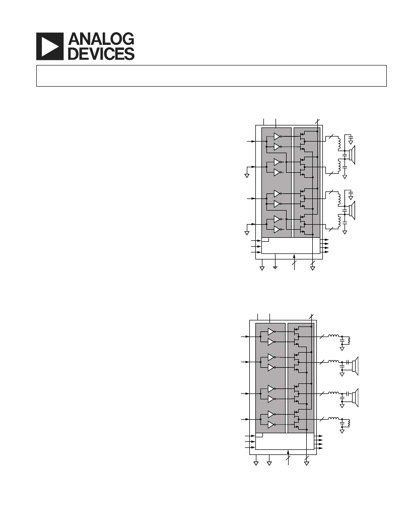
FUNCTIONAL BLOCK DIAGRAMS
2-Channel Mode
INA
LEFT
INPUT
INB
LEVEL SHIFTER
AND
SWITCH CONTROL
H-BRIDGE
AGND DGND
AV
DD
DV
DD
PV
DD
TEST
CONTROL
PGND
A1
A2
B1
B2
C1
C2
D1
D2
OUTA
3
OUTB
3
OUTC
3
OUTD
3
INC
IND
RIGHT
INPUT
CLK
RST
/
PDN
MUTE
CURRENT OVERLOAD
THERMAL SHUTDOWN
THERMAL WARNING
DATA LOSS
2
14
4
6
THERMAL PROTECTION
n
4-Channel Mode
INA
INB
LEVEL SHIFTER
AND
SWITCH CONTROL
H-BRIDGE
AGND DGND
AV
DD
DV
DD
PV
DD
TEST
CONTROL
PGND
A1
B1
B2
C1
C2
D1
D2
INC
IND
CLK
RST
/
PDN
MUTE
CURRENT OVERLOAD
THERMAL SHUTDOWN
THERMAL WARNING
DATA LOSS
2
4
14
6
THERMAL PROTECTION
n
OUTA
3
LOAD
OUTD
3
LOAD
OUTB
3
OUTC
3
FEATURES
Class D/1-Bit Audio Power Output Stage
5 V Analog and Digital Supply Voltages
Power Stage Power Supply 8 V to 20 V
Output Power @ 0.1% THD + N
Stereo Mode
2 20 W @ 4
@ 14.4 V
2 20 W @ 8
@ 20 V
Mono Mode
1 40 W @ 4
@ 20 V
R
ON
< 320 m
(per Transistor)
Efficiency > 85% @ Full Power/8
Clickless Mute Function
Turn-On and Turn-Off Pop Suppression
Short-Circuit Protection
Overtemperature Protection
Data Loss Protection
2-Channel BTL Outputs or
4-Channel Single-Ended Outputs
52-Lead Exposed Pad TQFP Package
Low Cost DMOS Process
APPLICATIONS
PC Audio Systems
Minicomponents
Automotive Amplifiers
Home Theater Systems
Televisions
GENERAL DESCRIPTION
The AD1991 is a 2-channel BTL or 4-channel single-ended
class D audio power output stage. The part is configured during
reset to be in either 2-channel mode or 4-channel mode.
To protect the IC as well as the connected speakers, the AD1991
provides turn-on and turn-off pop suppression, short-circuit
protection, and overtemperature shutdown. To control the IC,
a power-down/reset input and a mute pin are available.
The output stage can be operated over a power supply range
from 8 V to 20 V.
In 2-channel mode, Transistors A1, B2, C1, and D2 are turned
on by a Logic 1 on inputs INA and INC, and Transistors A2,
B1, C2, and D1 are turned on by a Logic 0 on inputs INA and
INC. In 4-channel mode, Transistors A1, B1, C1, and D1 are
turned on by a Logic 1 on the four inputs, and Transistors A2,
B2, C2, and D2 are turned on by a Logic 0 on the four inputs
(see the Functional Block Diagrams).
相關(guān)PDF資料 |
PDF描述 |
|---|---|
| AD1991 | Class D/1-Bit Audio Power Output Stage |
| AD1991ASVRL | Class D/1-Bit Audio Power Output Stage |
| AD1994ACPZRL | Audio Switching Amplifier |
| AD1994ACPZRL7 | Audio Switching Amplifier |
| AD203SN | Circular Connector; No. of Contacts:8; Series:LJTPQ00R; Body Material:Aluminum; Connecting Termination:Crimp; Connector Shell Size:17; Circular Contact Gender:Socket; Circular Shell Style:Wall Mount Receptacle |
相關(guān)代理商/技術(shù)參數(shù) |
參數(shù)描述 |
|---|---|
| AD1991ASVRL | 制造商:Analog Devices 功能描述:Audio Amp Speaker 1-CH Mono/2-CH Stereo/4-CH Stereo 40W Class-D 52-Pin TQFP T/R |
| AD1991ASVZ | 制造商:Analog Devices 功能描述:Audio Amp Speaker 1-CH Mono/2-CH Stereo/4-CH Stereo 40W Class-D 52-Pin TQFP 制造商:Analog Devices 功能描述:AUDIO POWER O/P STAGE CLASS D 1991 |
| AD1991ASVZRL | 制造商:Analog Devices 功能描述:Audio Amp Speaker 1-CH Mono/2-CH Stereo/4-CH Stereo 40W Class-D 52-Pin TQFP T/R |
| AD1992 | 制造商:AD 制造商全稱:Analog Devices 功能描述:Audio Switching Amplifier |
| AD1992_06 | 制造商:AD 制造商全稱:Analog Devices 功能描述:Audio Switching Amplifier |
發(fā)布緊急采購,3分鐘左右您將得到回復(fù)。