- 您現(xiàn)在的位置:買賣IC網(wǎng) > PDF目錄362070 > ACT-700SC-200F17T Microprocessor PDF資料下載
參數(shù)資料
| 型號(hào): | ACT-700SC-200F17T |
| 英文描述: | Microprocessor |
| 中文描述: | 微處理器 |
| 文件頁(yè)數(shù): | 3/24頁(yè) |
| 文件大小: | 227K |
| 代理商: | ACT-700SC-200F17T |
第1頁(yè)第2頁(yè)當(dāng)前第3頁(yè)第4頁(yè)第5頁(yè)第6頁(yè)第7頁(yè)第8頁(yè)第9頁(yè)第10頁(yè)第11頁(yè)第12頁(yè)第13頁(yè)第14頁(yè)第15頁(yè)第16頁(yè)第17頁(yè)第18頁(yè)第19頁(yè)第20頁(yè)第21頁(yè)第22頁(yè)第23頁(yè)第24頁(yè)
Aeroflex Circuit Technology
SCD7000 REV A 3/16/00 Plainview NY (516) 694-6700
3
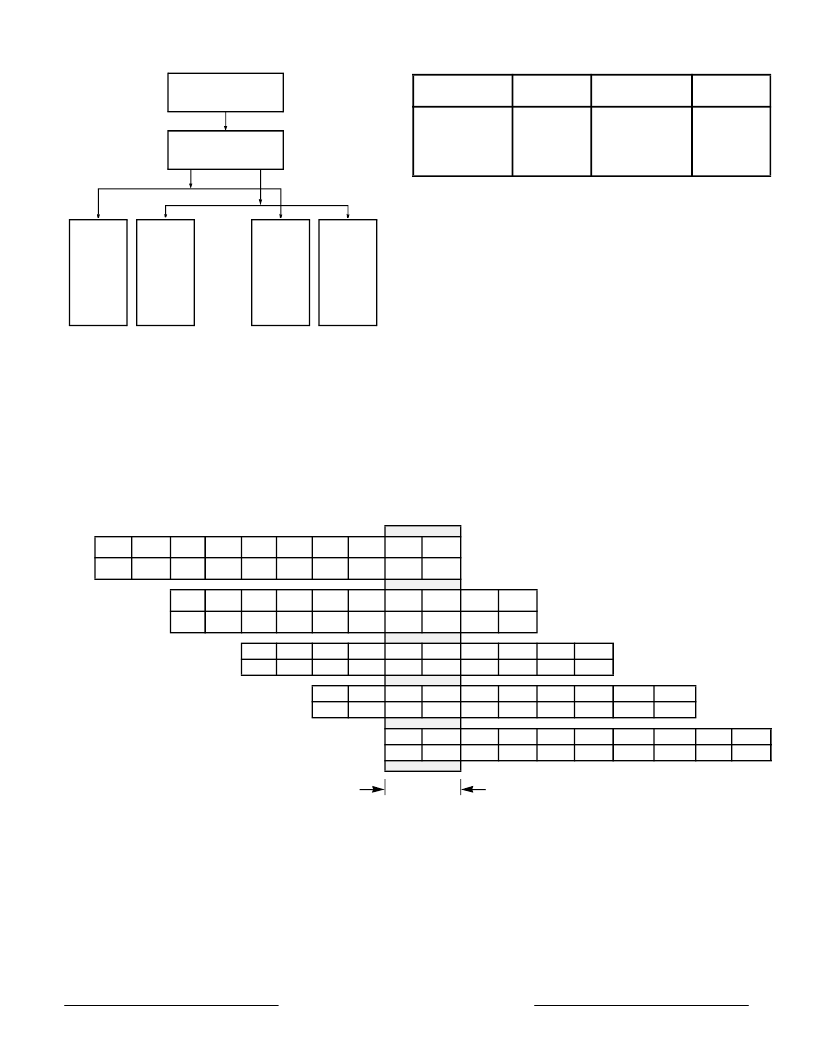
The figure illustrates that one F pipe instruction and
one M pipe instruction can be issued concurrently but
that two M pipe or two F pipe instructions cannot be
issued. Table 2 specifies more completely the
instructions within each class.
.
The symmetric superscalar capability of the ACT
7000SC, in combination with its low latency integer
execution units and high-throughput fully pipelined
floating-point execution unit, provides unparalleled
price/performance
in
embedded applications.
Pipeline
The logical length of both the F and M pipelines is
five stages with state committing in the register write,
or W, pipe stage. The physical length of the
floating-point execution pipeline is actually seven
stages but this is completely transparent to the user.
Figure 3 shows instruction execution within the
ACT 7000SC
when
instructions
simultaneously down both pipelines. As illustrated in
the figure, up to ten instructions can be executing
simultaneously. This figure presents a somewhat
simplistic view of the processors operation however
since the out-of-order completion of loads, stores, and
computational
intensive
are
issuing
Figure 2 – Instruction Issue Paradigm
FP
F Pipe
F Pipe IBus
M Pipe IBus
FP
M Pipe
Integer
F Pipe
Integer
M Pipe
Dispatch
Unit
Instruction
Cache
Table 2 – Dual Issue Instruction Classes
integer
load/store
floating-point
branch
add, sub, or, xor,
shift, etc.
lw, sw, ld, sd,
ldc1, sdc1,
mov, movc,
fmov, etc.
fadd, fsub, fmult,
fmadd, fdiv, fcmp,
fsqrt, etc.
beq, bne,
bCzT, bCzF, j,
etc.
I0
I1
1l
1l
2l
2l
1R
1R
2R
2R
1A
1A
2A
2A
1D
1D
2D
2D
1W
1W
2W
2W
I2
I3
1l
1l
2l
2l
1R
1R
2R
2R
1A
1A
2A
2A
1D
1D
2D
2D
1W
1W
2W
2W
I4
I5
1l
1l
2l
2l
1R
1R
2R
2R
1A
1A
2A
2A
1D
1D
2D
2D
1W
1W
2W
2W
I6
I7
1l
1l
2l
2l
1R
1R
2R
2R
1A
1A
2A
2A
1D
1D
2D
2D
1W
1W
2W
2W
I8
I9
1l
1l
2l
2l
1R
1R
2R
2R
1A
1A
2A
2A
1D
1D
2D
2D
1W
1W
2W
2W
one cycle
1I-1R:
2I:
2R:
1A:
1A:
1A-2A:
2A:
2A-2D:
1D:
2W:
Instruction cache access
Instruction virtual to physical address translation
Register file read, Bypass calculation, Instruction decode, Branch address calculation
Issue or slip decision, Branch decision
Data virtual address calculation
Integer add, logical, shift
Store Align
Data cache access and load align
Data virtual to physical address translation
Register file write
Figure 3 – Pipeline
Powered by ICminer.com Electronic-Library Service CopyRight 2003
相關(guān)PDF資料 |
PDF描述 |
|---|---|
| ACT-700SC-200F24C | Microprocessor |
| ACT-700SC-200F24I | Microprocessor |
| ACT-700SC-200F24M | Microprocessor |
| ACT-700SC-200F24Q | Microprocessor |
| ACT-700SC-200F24T | Microprocessor |
相關(guān)代理商/技術(shù)參數(shù) |
參數(shù)描述 |
|---|---|
| ACT-700SC-200F24C | 制造商:未知廠家 制造商全稱:未知廠家 功能描述:Microprocessor |
| ACT-700SC-200F24I | 制造商:未知廠家 制造商全稱:未知廠家 功能描述:Microprocessor |
| ACT-700SC-200F24M | 制造商:未知廠家 制造商全稱:未知廠家 功能描述:Microprocessor |
| ACT-700SC-200F24Q | 制造商:未知廠家 制造商全稱:未知廠家 功能描述:Microprocessor |
| ACT-700SC-200F24T | 制造商:未知廠家 制造商全稱:未知廠家 功能描述:Microprocessor |
發(fā)布緊急采購(gòu),3分鐘左右您將得到回復(fù)。