- 您現(xiàn)在的位置:買(mǎi)賣(mài)IC網(wǎng) > PDF目錄375225 > AC12FGML Thyristor Product Catalog PDF資料下載
參數(shù)資料
| 型號(hào): | AC12FGML |
| 英文描述: | Thyristor Product Catalog |
| 中文描述: | 晶閘管產(chǎn)品目錄 |
| 文件頁(yè)數(shù): | 165/224頁(yè) |
| 文件大小: | 2697K |
| 代理商: | AC12FGML |
第1頁(yè)第2頁(yè)第3頁(yè)第4頁(yè)第5頁(yè)第6頁(yè)第7頁(yè)第8頁(yè)第9頁(yè)第10頁(yè)第11頁(yè)第12頁(yè)第13頁(yè)第14頁(yè)第15頁(yè)第16頁(yè)第17頁(yè)第18頁(yè)第19頁(yè)第20頁(yè)第21頁(yè)第22頁(yè)第23頁(yè)第24頁(yè)第25頁(yè)第26頁(yè)第27頁(yè)第28頁(yè)第29頁(yè)第30頁(yè)第31頁(yè)第32頁(yè)第33頁(yè)第34頁(yè)第35頁(yè)第36頁(yè)第37頁(yè)第38頁(yè)第39頁(yè)第40頁(yè)第41頁(yè)第42頁(yè)第43頁(yè)第44頁(yè)第45頁(yè)第46頁(yè)第47頁(yè)第48頁(yè)第49頁(yè)第50頁(yè)第51頁(yè)第52頁(yè)第53頁(yè)第54頁(yè)第55頁(yè)第56頁(yè)第57頁(yè)第58頁(yè)第59頁(yè)第60頁(yè)第61頁(yè)第62頁(yè)第63頁(yè)第64頁(yè)第65頁(yè)第66頁(yè)第67頁(yè)第68頁(yè)第69頁(yè)第70頁(yè)第71頁(yè)第72頁(yè)第73頁(yè)第74頁(yè)第75頁(yè)第76頁(yè)第77頁(yè)第78頁(yè)第79頁(yè)第80頁(yè)第81頁(yè)第82頁(yè)第83頁(yè)第84頁(yè)第85頁(yè)第86頁(yè)第87頁(yè)第88頁(yè)第89頁(yè)第90頁(yè)第91頁(yè)第92頁(yè)第93頁(yè)第94頁(yè)第95頁(yè)第96頁(yè)第97頁(yè)第98頁(yè)第99頁(yè)第100頁(yè)第101頁(yè)第102頁(yè)第103頁(yè)第104頁(yè)第105頁(yè)第106頁(yè)第107頁(yè)第108頁(yè)第109頁(yè)第110頁(yè)第111頁(yè)第112頁(yè)第113頁(yè)第114頁(yè)第115頁(yè)第116頁(yè)第117頁(yè)第118頁(yè)第119頁(yè)第120頁(yè)第121頁(yè)第122頁(yè)第123頁(yè)第124頁(yè)第125頁(yè)第126頁(yè)第127頁(yè)第128頁(yè)第129頁(yè)第130頁(yè)第131頁(yè)第132頁(yè)第133頁(yè)第134頁(yè)第135頁(yè)第136頁(yè)第137頁(yè)第138頁(yè)第139頁(yè)第140頁(yè)第141頁(yè)第142頁(yè)第143頁(yè)第144頁(yè)第145頁(yè)第146頁(yè)第147頁(yè)第148頁(yè)第149頁(yè)第150頁(yè)第151頁(yè)第152頁(yè)第153頁(yè)第154頁(yè)第155頁(yè)第156頁(yè)第157頁(yè)第158頁(yè)第159頁(yè)第160頁(yè)第161頁(yè)第162頁(yè)第163頁(yè)第164頁(yè)當(dāng)前第165頁(yè)第166頁(yè)第167頁(yè)第168頁(yè)第169頁(yè)第170頁(yè)第171頁(yè)第172頁(yè)第173頁(yè)第174頁(yè)第175頁(yè)第176頁(yè)第177頁(yè)第178頁(yè)第179頁(yè)第180頁(yè)第181頁(yè)第182頁(yè)第183頁(yè)第184頁(yè)第185頁(yè)第186頁(yè)第187頁(yè)第188頁(yè)第189頁(yè)第190頁(yè)第191頁(yè)第192頁(yè)第193頁(yè)第194頁(yè)第195頁(yè)第196頁(yè)第197頁(yè)第198頁(yè)第199頁(yè)第200頁(yè)第201頁(yè)第202頁(yè)第203頁(yè)第204頁(yè)第205頁(yè)第206頁(yè)第207頁(yè)第208頁(yè)第209頁(yè)第210頁(yè)第211頁(yè)第212頁(yè)第213頁(yè)第214頁(yè)第215頁(yè)第216頁(yè)第217頁(yè)第218頁(yè)第219頁(yè)第220頁(yè)第221頁(yè)第222頁(yè)第223頁(yè)第224頁(yè)
Application Notes
AN1006
2002 Teccor Electronics
Thyristor Product Catalog
AN1006 - 13
http://www.teccor.com
+1 972-580-7777
Procedure 11: I
H(Forward and Reverse)
For these steps, it is again necessary to connect the
Trigger
to
MT2
through a 10
resistor. The other connections remain the
same.
To measure the I
H (Forward and Reverse)
parameter:
1. Set
Power Dissipation
to
50 W.
2. Set
Max Peak Volts
to
75 V.
(
80 V
on 370)
3. Set
Mode
to
DC
.
4. Set
Horizontal
knob to
5 V/DIV.
5. Set
Vertical
knob to approximately 10% of the maximum I
H
specified.
Note: Due to large variations of holding current values, the
scale may have to be adjusted to observe holding current.
6. Set
Terminal Selector
to
Emitter Grounded-Open Base.
Procedure 12: I
H(Forward)
To measure the I
H (Forward)
parameter:
1. Set
Polarity
to (+).
2. Set
Left-Right Terminal Jack Selector
to correspond with
the location of the test fixture.
3. Increase
Variable Collector Supply Voltage
to maximum
position (
100
).
Note: Depending on the vertical scale being used, the dot
may disappear completely from the screen.
4. Decrease
Variable Collector Supply Voltage
to the point
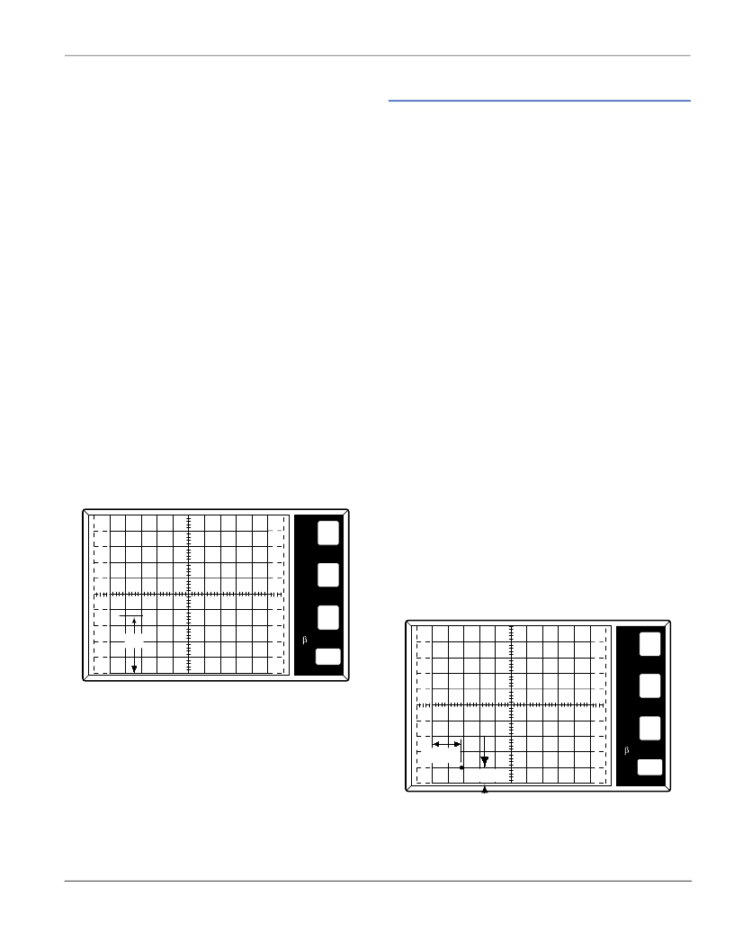
where the line on the CRT changes to a dot. The position of
the beginning point of the line, just before the line changes to
a dot, represents the I
H
value. (Figure AN1006.21)
Figure AN1006.21 I
H (Forward)
= 18 mA
Procedure 13: I
H(Reverse)
To measure the I
H (Reverse)
parameter:
1. Set
Polarity
to (–).
2. Continue testing per Procedure 12 for measuring I
H (Reverse)
.
Sidacs
The sidac is a bidirectional voltage-triggered switch. Upon appli-
cation of a voltage exceeding the sidac breakover voltage point,
the sidac switches on through a negative resistance region (simi-
lar to a diac) to a low on-state voltage. Conduction continues until
current is interrupted or drops below minimum required holding
current.
To connect the sidac:
1. Connect
MT1
to the
Emitter Terminal
(E).
2. Connect
MT2
to the
Collector Terminal
(C).
To begin testing, perform the following procedures.
Procedure 1: (+) V
DRM
, (+)I
DRM
, (-)V
DRM
, (-)I
DRM
Note: The (+) and (-) symbols are used to designate the polarity
of MT2 with reference to MT1.
To measure the (+)V
DRM
, (+)I
DRM
, (-)V
DRM
, and (-)I
DRM
parameter:
1. Set
Variable Collector Supply Voltage Range
to
1500 Max
Peak Volts
.
2. Set
Horizontal
knob to
50 V/DIV.
3. Set
Mode
to
Leakage
.
4. Set
Polarity
to (+).
5. Set
Power Dissipation
to
2.2 W
. (
2 W
on 370)
6. Set
Terminal Selector
to
Emitter Grounded-Open Base
.
7. Set
Vertical
knob to
50 μA/DIV.
(Due to leakage mode, the
CRT readout will show 50 nA.)
Procedure 2: (+)V
DRM
and (+)I
DRM
To measure the (+)V
DRM
and (+)I
DRM
parameter:
1. Set
Left-Right Terminal Jack Selector
to correspond with
the location of the test fixture.
2. Increase
Variable Collector Supply Voltage
to the rated
V
DRM
of the device and observe the dot on the CRT. Read
across horizontally from the dot to the vertical current scale.
This measured value is the leakage current.
(Figure AN1006.22)
Figure AN1006.22 I
DRM
= 50 nA at V
DRM
= 90 V
5
mA
5
V
PER
V
E
R
T
DIV
PER
H
O
R
I
Z
DIV
PER
S
T
E
P
()k
DIV
9m
PER
DIV
IH
50
nA
50
V
PER
V
E
R
T
DIV
PER
H
O
R
I
Z
DIV
PER
S
T
E
P
()k
DIV
9m
PER
DIV
VDRM
IDRM
相關(guān)PDF資料 |
PDF描述 |
|---|---|
| AC12FSM | Thyristor Product Catalog |
| AC16BGM | Thyristor Product Catalog |
| AC16BSM | Thyristor Product Catalog |
| AC16DGM | Thyristor Product Catalog |
| AC16DSM | HEAT SINK, TO-220, 25 C/W; Case style:TO-220; Thermal resistance:25(degree C)/W; Width, external:12.7mm; Depth, external:19.5mm; Length / Height, external:12.7mm; Material:Aluminium; Surface finish:Black Anodised; Fixing RoHS Compliant: Yes |
相關(guān)代理商/技術(shù)參數(shù) |
參數(shù)描述 |
|---|---|
| AC12FSM | 制造商:TECCOR 制造商全稱:TECCOR 功能描述:Thyristor Product Catalog |
| AC12FSMA | 制造商:NEC 制造商全稱:NEC 功能描述:12A RESIN INSULATION TYPE TRIAC |
| AC12FSMA(AZ) | 制造商:Renesas Electronics Corporation 功能描述: |
| AC12ZD0223MBB | 制造商:STMicroelectronics 功能描述: 制造商:THOMSON 功能描述: |
| AC-13 | 制造商:Kitagawa Industries 功能描述:Pack |
發(fā)布緊急采購(gòu),3分鐘左右您將得到回復(fù)。