- 您現(xiàn)在的位置:買賣IC網(wǎng) > PDF目錄375225 > AC12BSM Thyristor Product Catalog PDF資料下載
參數(shù)資料
| 型號(hào): | AC12BSM |
| 英文描述: | Thyristor Product Catalog |
| 中文描述: | 晶閘管產(chǎn)品目錄 |
| 文件頁數(shù): | 167/224頁 |
| 文件大?。?/td> | 2697K |
| 代理商: | AC12BSM |
第1頁第2頁第3頁第4頁第5頁第6頁第7頁第8頁第9頁第10頁第11頁第12頁第13頁第14頁第15頁第16頁第17頁第18頁第19頁第20頁第21頁第22頁第23頁第24頁第25頁第26頁第27頁第28頁第29頁第30頁第31頁第32頁第33頁第34頁第35頁第36頁第37頁第38頁第39頁第40頁第41頁第42頁第43頁第44頁第45頁第46頁第47頁第48頁第49頁第50頁第51頁第52頁第53頁第54頁第55頁第56頁第57頁第58頁第59頁第60頁第61頁第62頁第63頁第64頁第65頁第66頁第67頁第68頁第69頁第70頁第71頁第72頁第73頁第74頁第75頁第76頁第77頁第78頁第79頁第80頁第81頁第82頁第83頁第84頁第85頁第86頁第87頁第88頁第89頁第90頁第91頁第92頁第93頁第94頁第95頁第96頁第97頁第98頁第99頁第100頁第101頁第102頁第103頁第104頁第105頁第106頁第107頁第108頁第109頁第110頁第111頁第112頁第113頁第114頁第115頁第116頁第117頁第118頁第119頁第120頁第121頁第122頁第123頁第124頁第125頁第126頁第127頁第128頁第129頁第130頁第131頁第132頁第133頁第134頁第135頁第136頁第137頁第138頁第139頁第140頁第141頁第142頁第143頁第144頁第145頁第146頁第147頁第148頁第149頁第150頁第151頁第152頁第153頁第154頁第155頁第156頁第157頁第158頁第159頁第160頁第161頁第162頁第163頁第164頁第165頁第166頁當(dāng)前第167頁第168頁第169頁第170頁第171頁第172頁第173頁第174頁第175頁第176頁第177頁第178頁第179頁第180頁第181頁第182頁第183頁第184頁第185頁第186頁第187頁第188頁第189頁第190頁第191頁第192頁第193頁第194頁第195頁第196頁第197頁第198頁第199頁第200頁第201頁第202頁第203頁第204頁第205頁第206頁第207頁第208頁第209頁第210頁第211頁第212頁第213頁第214頁第215頁第216頁第217頁第218頁第219頁第220頁第221頁第222頁第223頁第224頁
Application Notes
AN1006
2002 Teccor Electronics
Thyristor Product Catalog
AN1006 - 15
http://www.teccor.com
+1 972-580-7777
To continue testing, perform the following procedures.
Procedure 9: V
TM(Forward)
To measure the V
TM (Forward)
parameter:
1. Set
Left-Right Terminal Jack Selector
to correspond with
the location of the test fixture.
2. Increase
Variable Collector Supply Voltage
until current
reaches rated I
T(peak)
, which is 1.4 times the I
T(RMS)
rating of
the sidac.
Note: Model 370 current is limited. Set to 400 mA. Check for
1.1 V MAX.
WARNING: Limit test time to 15 seconds.
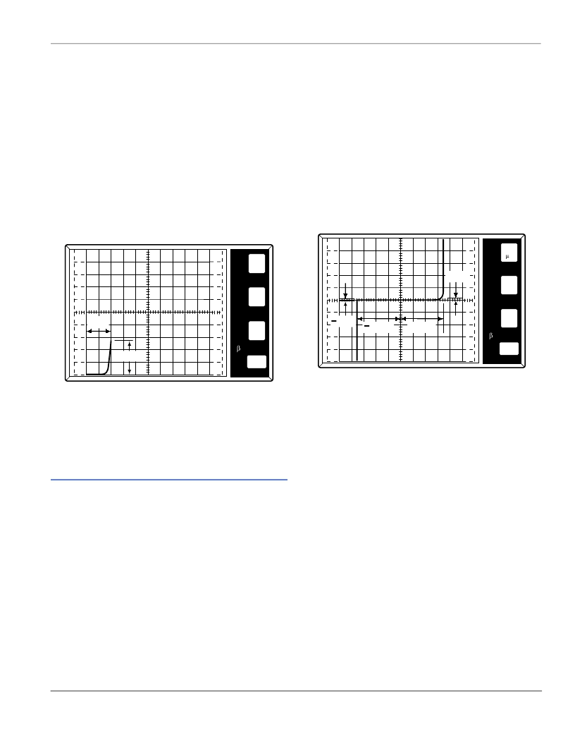
3. To measure V
TM
, follow along horizontal scale to the point
where the trace crosses the I
T(peak)
value. This horizontal dis-
tance is the V
TM
value. (Figure AN1006.25)
Figure AN1006.25 V
TM (Forward)
= 950 mV at I
= 1.4 A
Procedure 10: V
TM(Reverse)
To measure the V
TM (Reverse)
parameter:
1. Set
Polarity
to (–).
2. Repeat Procedure 8 to measure V
TM(Reverse)
.
Diacs
Diacs are voltage breakdown switches used to trigger-on triacs
and non-sensitive SCRs in phase control circuits.
Note: Diacs are bi-directional devices and can be connected in
either direction.
To connect the diac:
1. Connect one side of the diac to the
Collector Terminal
(C).
2. Connect other side of the diac to the
Emitter Terminal
(E).
To begin testing, perform the following procedures.
Procedure 1: Curve Tracer Setup
To set the curve tracer and begin testing:
1. Set
Variable Collector Supply Voltage Range
to
75 Max
Peak Volts.
(
80 V
on 370)
2. Set
Horizontal
knob to sufficient scale to allow viewing of
trace at the required voltage level (
10 V to 20 V/DIV
depend-
ing on device being tested).
3. Set
Vertical
knob to
50 μA/DIV.
4. Set
Polarity
to
AC.
5. Set
Mode
to
Norm.
6. Set
Power Dissipation
to
0.5 W
. (
0.4 W
on 370)
7. Set
Terminal Selector
to
Emitter Grounded-Open Base.
Procedure 2: V
BO
To measure the V
BO
parameter:
1. Set
Left-Right Terminal Jack Selector
to correspond with
the location of the test fixture.
2. Set
Variable Collector Supply Voltage
to
55 V
(
65 V
for
370) and apply voltage to device under test (D.U.T.), using
Left-Right-Selector Switch
. The peak voltage at which cur-
rent begins to flow is the V
BO
value. (Figure AN1006.26)
Figure AN1006.26 (+)V
BO
= 35 V; (-)V
BO
= 36 V; (±)I
BO
< 15 μA;
(-)I
BO
< 10 μA and Cannot Be Read Easily
Procedure 3: I
BO
To measure the I
BO
parameter, at the V
BO
point, measure the
amount of device current just before the device reaches the
breakover mode. The measured current at this point is the I
BO
value.
Note: If I
is less than 10 μA, the current cannot readily be seen
on the curve tracer.
Procedure 4:
V
BO(Voltage Breakover Symmetry)
To measure the
V
BO (Voltage Breakover Symmetry)
parameter:
1. Measure positive and negative values of V
BO
as shown in
Figure AN1006.26.
2. Subtract the absolute value of V
BO
(-) from V
BO
(+).
The absolute value of the result is:
V
BO
= [ I +V
BO
I - I -V
BO
I ]
500
mA
500
mV
PER
V
E
R
T
DIV
PER
H
O
R
I
Z
DIV
PER
S
T
E
P
()k
DIV
9m
PER
DIV
VTM
IPK
50
A
10
V
PER
V
E
R
T
DIV
PER
H
O
R
I
Z
DIV
PER
S
T
E
P
()k
DIV
9m
PER
DIV
+VBO
+IBO
IBO
VBO
相關(guān)PDF資料 |
PDF描述 |
|---|---|
| AC12DGML | Thyristor Product Catalog |
| AC12DSM | MAX CLIP RoHS Compliant: Yes NC/NR |
| AC12EGML | Thyristor Product Catalog |
| AC12ESM | Thyristor Product Catalog |
| AC12FGML | Thyristor Product Catalog |
相關(guān)代理商/技術(shù)參數(shù) |
參數(shù)描述 |
|---|---|
| AC12DGM | 制造商:NEC 制造商全稱:NEC 功能描述:12A MOLD TRIAC |
| AC12DGML | 制造商:TECCOR 制造商全稱:TECCOR 功能描述:Thyristor Product Catalog |
| AC12DSM | 制造商:TECCOR 制造商全稱:TECCOR 功能描述:Thyristor Product Catalog |
| AC12DSMA | 制造商:NEC 制造商全稱:NEC 功能描述:12A RESIN INSULATION TYPE TRIAC |
| AC12DSMA(AZ) | 制造商:Renesas Electronics Corporation 功能描述: |
發(fā)布緊急采購,3分鐘左右您將得到回復(fù)。