- 您現(xiàn)在的位置:買賣IC網(wǎng) > PDF目錄375206 > AAT3512IGV-4.20-C-C-T1 (Electronic Theatre Controls, Inc.) Micropower uP Reset with Watchdog Timer PDF資料下載
參數(shù)資料
| 型號(hào): | AAT3512IGV-4.20-C-C-T1 |
| 廠商: | Electronic Theatre Controls, Inc. |
| 元件分類: | 復(fù)位半導(dǎo)體 |
| 英文描述: | Micropower uP Reset with Watchdog Timer |
| 中文描述: | 微功耗 μP 復(fù)位和看門狗定時(shí)器 |
| 文件頁(yè)數(shù): | 2/12頁(yè) |
| 文件大?。?/td> | 157K |
| 代理商: | AAT3512IGV-4.20-C-C-T1 |
AAT3510/1/2/3/4/5/6/7/8/9
Micropower μP Reset with Watchdog Timer
2
3510.2004.08.1.4
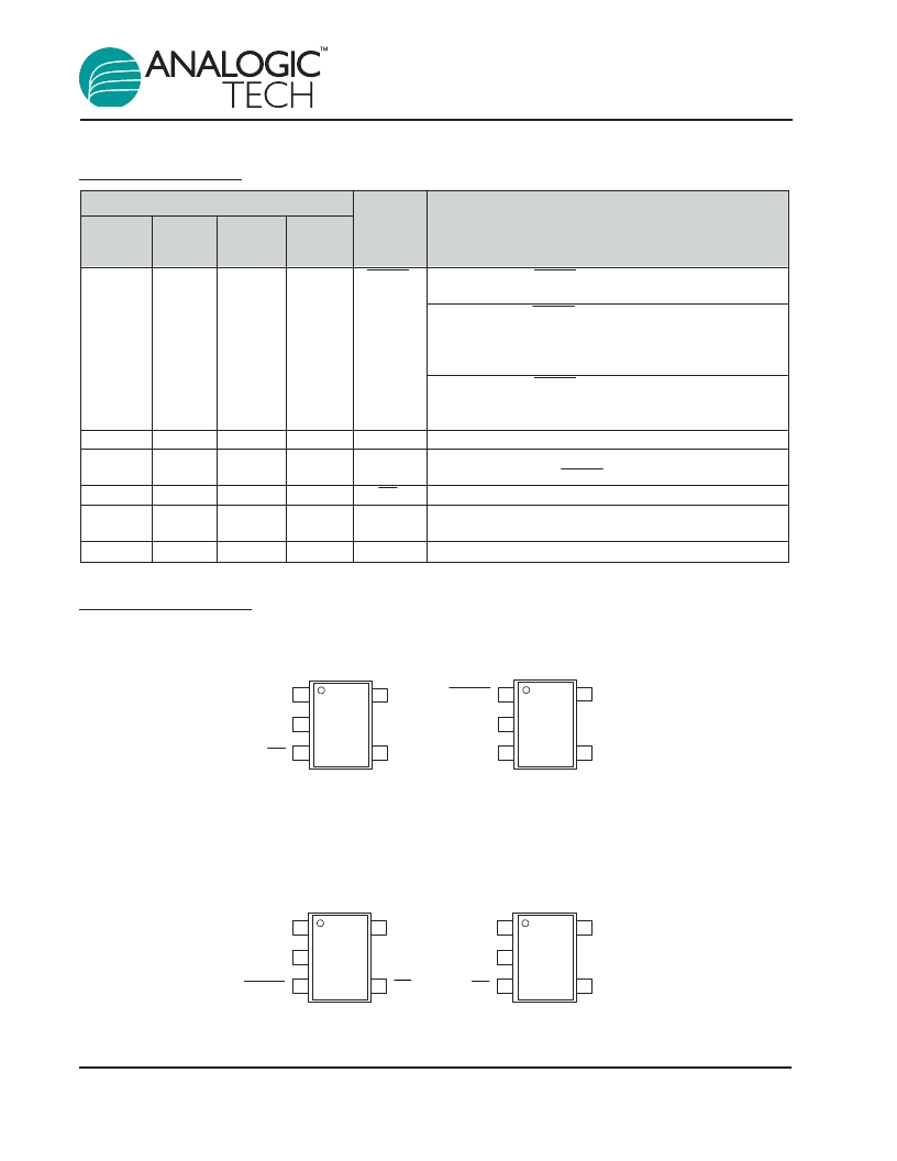
Pin Descriptions
Pin Configuration
(Top View)
AAT3516
AAT3519
(Top View)
AAT3510
AAT3511
AAT3517
(Top View)
AAT3513
AAT3514
AAT3518
(Top View)
AAT3512
AAT3515
5-lead SOT23
5-lead SOT23
5-lead SOT23
5-lead SOT23
GND
V
CC
WDI
MR
RESET
1
2
3
4
5
GND
V
CC
MR
RESET
RESET
1
2
3
4
5
GND
V
CC
WDI
MR
RESET
1
2
3
4
5
GND
V
CC
WDI
RESET
RESET
1
2
3
4
5
Pin #
AAT3510
AAT3511
AAT3517
AAT3512 AAT3513
AAT3515
AAT3516
AAT3519
AAT3514
AAT3518
Symbol
Function
1
N/A
1
1
RESET
AAT3510/13/15: RESET output goes low whenever V
DD
falls below the reset threshold. CMOS push-pull Output
AAT3511/14/16: RESET output goes low whenever V
DD
falls below the reset threshold. Bidirectional CMOS push-
pull Output intended to interface directly to microproces-
sors with bi-directional resets
AAT3517/18/19: RESET output goes low whenever V
DD
falls below the reset threshold. Open drain output. Connect
a pull-up resistor to any supply voltage up to 5.5V
Ground connection pin
RESET active-high output. This CMOS push-pull signal is
the logical inverse of RESET.
Manual reset input pin. Active low. Pull low to force a reset.
Watchdog input pin. Triggers a reset if it remains in a
steady state for the duration of the watchdog timer period.
Input voltage pin
2
2
1
2
3
2
3
GND
RESET
3
4
3
4
N/A
4
4
MR
WDI
N/A
5
5
5
5
V
CC
相關(guān)PDF資料 |
PDF描述 |
|---|---|
| AAT3512IGV-4.38-A-A-T1 | Micropower uP Reset with Watchdog Timer |
| AAT3512IGV-4.38-A-B-T1 | Micropower uP Reset with Watchdog Timer |
| AAT3512IGV-4.38-A-C-T1 | Micropower uP Reset with Watchdog Timer |
| AAT3512IGV-4.38-B-B-T1 | Micropower uP Reset with Watchdog Timer |
| AAT3512IGV-4.38-B-C-T1 | Micropower uP Reset with Watchdog Timer |
相關(guān)代理商/技術(shù)參數(shù) |
參數(shù)描述 |
|---|---|
| AAT3515IGV-2.63-C-T1 | 制造商:Skyworks Solutions Inc 功能描述:POWER MANAGEMENT IC |
| AAT3515IGV-3.08-C-T1 | 制造商:Skyworks Solutions Inc 功能描述:POWER MANAGEMENT IC |
| AAT3517IGV-2.93-C-C-T1 | 功能描述:監(jiān)控電路 MicroPower Micro- prcsr Reset Circuit RoHS:否 制造商:Maxim Integrated 監(jiān)測(cè)電壓數(shù): 監(jiān)測(cè)電壓: 欠電壓閾值: 過電壓閾值: 輸出類型: 人工復(fù)位: 監(jiān)視器: 電池備用開關(guān): 上電復(fù)位延遲(典型值): 電源電壓-最大: 最大工作溫度: 安裝風(fēng)格: 封裝 / 箱體: 封裝: |
| AAT3522IGY-2.32-200-T1 | 制造商:Skyworks Solutions Inc 功能描述:POWER MANAGEMENT IC |
| AAT3522IGY-2.93-200-T1 | 制造商:Skyworks Solutions Inc 功能描述:POWER MANAGEMENT IC 制造商:Skyworks 功能描述:ANALOG IC |
發(fā)布緊急采購(gòu),3分鐘左右您將得到回復(fù)。