- 您現(xiàn)在的位置:買賣IC網(wǎng) > PDF目錄362041 > AA2020A Controller Miscellaneous - Datasheet Reference PDF資料下載
參數(shù)資料
| 型號: | AA2020A |
| 英文描述: | Controller Miscellaneous - Datasheet Reference |
| 中文描述: | 控制器雜項-數(shù)據(jù)表參考 |
| 文件頁數(shù): | 3/7頁 |
| 文件大小: | 296K |
| 代理商: | AA2020A |
(VOLTS)
(VOLTS)
(VOLTS)
3
4
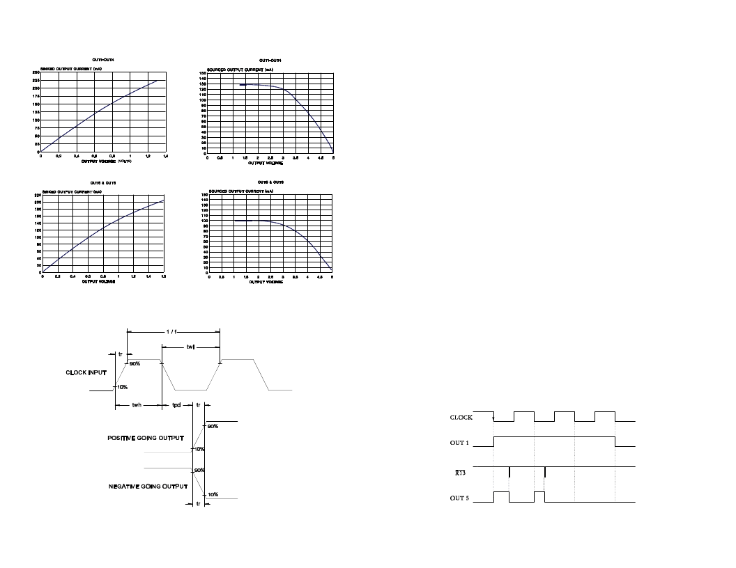
Figure 3: Input/Output Waveform Characteristics
TYPICAL OUTPUT CHARACTERISTICS
Figure 4: High Voltage Output (OUT5) vs. Reset
(R13) and OUT1.
BILEVEL DRIVE
The basic function of a step motor driver is to control the motor winding
currents. Motor performance is determined by how fast the driver can
increase and decrease the winding currents. A rapid rise in winding current is
achieved by applying a high voltage directly to a motor. This rapid rise of
current is also referred to as the "kick" or operating current. When a desired
current level is reached, a low voltage is applied to maintain a suitable holding
current level. When a motor winding is turned off, a rapid decrease in winding
current is achieved by routing the energy in the collapsing field back to the
power supply through a high voltage path. The high voltage supply furnishes
the energy necessary to maintain motor output torque at high step rates thus
providing high mechanical power output. The low voltage supply provides
much of the current needed at low step rates and all of the holding current.
The efficiency of bilevel drive makes for step motor performance that is far
superior to that produced by L/R drives. Also, bilevel drivers do not use high
frequency switching techniques as chopper drivers do. Consequently, they do
not create the EMI, RFI, and motor heating problems that are associated with
chopper drivers.
AA2020 Operation
Each time the chip receives a clock signal, the phase outputs change state.
When a phase output turns on, a high voltage output also turns on. This high
voltage output is used to turn on a high-side switch. The high voltage output
will stay on until the chip gets a reset signal. In Figure 4, OUT1 turns on when
the CLOCK input goes low. OUT5 turns on at the same time. OUT5 stays on
until the reset input, R13 goes low. The waveforms in Figure 4 are for half-
step operation. In half-step operation, the phase outputs are on for three clock
cycles. The high voltage output will turn on the first two of these cycles. If the
reset input never goes low, the high voltage output will stay on. In full-step
operation, each phase output is on for two clock cycles and the corresponding
high voltage output will turn on at the beginning of each clock cycle.
相關(guān)PDF資料 |
PDF描述 |
|---|---|
| AA2820 | Controller Miscellaneous - Datasheet Reference |
| AA20C-048L-0335-M1 | Analog IC |
| AA20C-048L-050S | Analog IC |
| AA20C-048L-050S1 | Analog IC |
| AA20C-048L-050S4 | Analog IC |
相關(guān)代理商/技術(shù)參數(shù) |
參數(shù)描述 |
|---|---|
| AA20-25 | 制造商:Alpha & Omega Semiconductor 功能描述: |
| AA203055 | 制造商:Hubbell Wiring Device-Kellems 功能描述:PS, IEC, RECP, ANGLE ADAPT, 20/30A |
| AA2030PS | 制造商:Hubbell Wiring Device-Kellems 功能描述:ps, ins, recp, angle adapter, 20/30A 制造商:Hubbell Wiring Device-Kellems 功能描述:Adapts 16, 20, 30 And 32A Watertight IEC Pin And Sleeve Devices To Standard Wall Boxes |
| AA203K | 制造商:ECLIPSE 功能描述:BLADE HIGH CUT 12X1X0.050X10TPI |
| AA204C | 制造商:ECLIPSE 功能描述:BLADE HIGH CUT 12X1X0.050X14TPI 制造商:ECLIPSE 功能描述:BLADE, HIGH CUT, 12X1X0.050X14TPI |
發(fā)布緊急采購,3分鐘左右您將得到回復(fù)。