- 您現(xiàn)在的位置:買賣IC網(wǎng) > PDF目錄366310 > A914BYW-470M (TOKO INC) Fixed Inductors for Surface Mounting PDF資料下載
參數(shù)資料
| 型號(hào): | A914BYW-470M |
| 廠商: | TOKO INC |
| 元件分類: | 通用定值電感 |
| 英文描述: | Fixed Inductors for Surface Mounting |
| 中文描述: | 1 ELEMENT, 47 uH, GENERAL PURPOSE INDUCTOR, SMD |
| 文件頁(yè)數(shù): | 1/1頁(yè) |
| 文件大?。?/td> | 105K |
| 代理商: | A914BYW-470M |

Fixed Inductors for Surface Mounting
Inductance Range:
1.2~100μH
SELECTION GUIDE FOR STANDARD COILS
DIMENSIONS
FEATURES
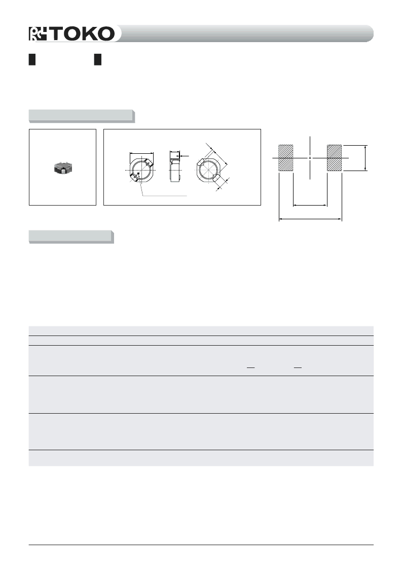
D52LC
Recommended patterns
42
5.2 Max.
06
14
2.0 Max.
0.15
Direction indication
Low profile (5.2mm Max. square, 2.0mm Max. height).
Magnetically shielded construction and low DC resistance.
Suitable for large currents.
Ideal for a variety of DC-DC converter inductor
applications.
RoHS compliant.
(1) Inductance is measured with a LCR meter 4284A (Agilent
Technologies) or equivalent.
Test frequency at 100kHz
(2) DC resistance is measured with a Digital Multimeter TR6871
(Advantest) or equivalent.
(3) Maximum allowable DC current is that which causes a 30%
inductance reduction from the initial value, or coil temperature to rise
by 40°C, whichever is smaller. (Reference ambient temperature
20°C)
TYPE D52LC
(Quantity/reel; 2,000 PCS)
Temperature
Rise Current
(3)
T=40°C
(A) Max. (Typ.)
#A914BYW-1R2M
#A914BYW-2R2M
#A914BYW-3R5M
#A914BYW-4R7M
#A914BYW-6R8M
1.2
2.2
3.5
4.7
6.8
±
20
±
20
±
20
±
20
±
20
44 (37)
59 (49)
73 (61)
87 (72)
105 (84)
1.94 (2.59)
1.44 (1.93)
1.19 (1.59)
1.01 (1.35)
0.83 (1.11)
2.15 (2.88)
1.63 (2.18)
1.34 (1.80)
1.14 (1.52)
0.95 (1.27)
2.44 (2.87)
1.74 (2.06)
1.54 (1.82)
1.30 (1.54)
1.17 (1.38)
#A914BYW-100M
#A914BYW-150M
#A914BYW-220M
#A914BYW-330M
#A914BYW-470M
10.0
15.0
22.0
33.0
47.0
±
20
±
20
±
20
±
20
±
20
150 (125)
210 (175)
275 (230)
455 (375)
730 (605)
0.67 (0.90)
0.56 (0.76)
0.49 (0.66)
0.39 (0.53)
0.32 (0.43)
0.76 (1.03)
0.63 (0.85)
0.56 (0.75)
0.44 (0.59)
0.36 (0.49)
0.93 (1.10)
0.77 (0.91)
0.70 (0.83)
0.51 (0.61)
0.38 (0.45)
#A914BYW-680M
#A914BY-101M
68.0
100.0
±
20
±
20
935 (780)
1500 (1250)
0.26 (0.35)
0.20 (0.28)
0.30 (0.41)
0.23 (0.32)
0.35 (0.42)
0.26 (0.31)
TOKO
Part
Number
Inductance
(1)
(μH)
DC
Resistance
(2)
(m
) Max.
(Typ.)
Inductance Decrease Current
(3)
(A) Max. (Typ.)
L
L
=10%
=30%
L
L
Tolerance
(%)
6.0
4.0
2
(Unit: mm)
(Unit: mm)
相關(guān)PDF資料 |
PDF描述 |
|---|---|
| A914BYW-4R7M | Fixed Inductors for Surface Mounting |
| A914BYW-680M | Fixed Inductors for Surface Mounting |
| A914BYW-6R8M | Fixed Inductors for Surface Mounting |
| A915AY-100M | Fixed Inductors for Surface Mounting |
| A915BY-6R8M | Fixed Inductors for Surface Mounting |
相關(guān)代理商/技術(shù)參數(shù) |
參數(shù)描述 |
|---|---|
| A914BYW-4R7M | 制造商:TOKO Inc XXX 功能描述:Inductor D52LC SMD 4.7uH 20% 1.14A |
| A914BYW-680M | 制造商:TOKO Inc 功能描述:Inductor D52LC SMD 68uH 20% 2300mA |
| A914BYW-6R8M | 制造商:TOKO Inc 功能描述:Inductor D52LC SMD 6.8uH 20% 950mA |
| A914PC100 | 制造商: 功能描述: 制造商:undefined 功能描述: |
| A9150017 | 制造商:Okw Enclosures 功能描述:Bulk |
發(fā)布緊急采購(gòu),3分鐘左右您將得到回復(fù)。