- 您現(xiàn)在的位置:買賣IC網(wǎng) > PDF目錄57457 > A3064LKA MAGNETIC FIELD SENSOR-HALL EFFECT, 1.25-2.75mT, 0.14-0.40V, RECTANGULAR, THROUGH HOLE MOUNT PDF資料下載
參數(shù)資料
| 型號(hào): | A3064LKA |
| 元件分類: | 磁阻傳感器 |
| 英文描述: | MAGNETIC FIELD SENSOR-HALL EFFECT, 1.25-2.75mT, 0.14-0.40V, RECTANGULAR, THROUGH HOLE MOUNT |
| 封裝: | PLASTIC, SIP-5 |
| 文件頁(yè)數(shù): | 6/9頁(yè) |
| 文件大小: | 783K |
| 代理商: | A3064LKA |
3064
HALL-EFFECT
GEAR-TOOTH SENSOR
—AC COUPLED
www.allegromicro.com
5
Figure 2
OP
B
= +15 G
B – B
E1
E2
GEAR
4300 G
4150 G
150 G
0 G
-150 G
RP
B
= 0 G
V
OUT(SAT)
V
OUT
B & B
E1
E2
OUTPUT DUTY CYCLE
≈ 50%
Dwg. WH-003-3
DIRECTION
OF ROTATION
LEADING
EDGE
TRAILING
EDGE
NORTH
SOUTH
E2
E1
(a)
(b)
(c)
low) when BE1 - BE2 < BRP. The difference between BOP and
BRP is the hysteresis of the device.
Note that powering up in the absence of a differential
magnetic field (less than the device BOP and higher than the
device BRP) will allow an indeterminate output state. The
correct output state is warranted after the first excursion beyond
BOP or BRP.
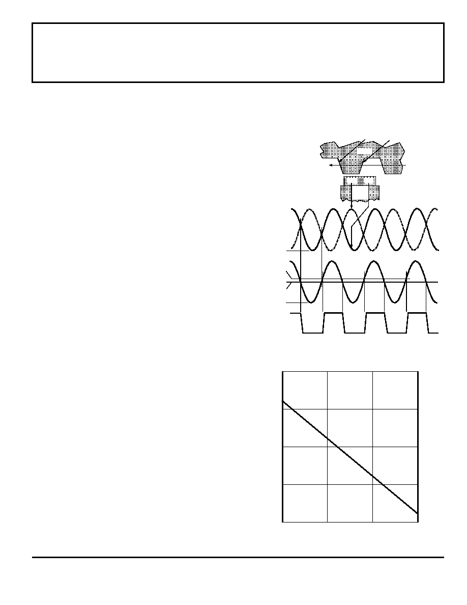
Figure 2 relates the output state of a back-biased sensor IC,
with switching characteristics shown in Figure 1, to the target
gear profile and position. Assume a north pole back-bias
configuration (equivalent to a south pole at the face of the
device). The motion of the gear produces a phase-shifted field
at E1 and E2 (Figure 2(a)); internal conditioning circuitry
subtracts the fields at the two elements (Figure 2(b)); this
differential field is band-pass filtered to remove dc offset
components and then fed into a Schmitt trigger; the Schmitt
trigger switches the output transistor at the thresholds BOP and
BRP. As shown (Figure 2(c)), the IC output is low whenever
sensor E2 faces a (ferrous) gear tooth and sensor E1 faces air.
The output is high when sensor E1 faces air and sensor E2 faces
a ferrous target.
AC-Coupled Operation. Steady-state magnet and
system offsets are eliminated using an on-chip differential band-
pass filter. The lower frequency cut-off of this patented filter is
set using an external capacitor, the value of which can range
from 0.01
F to 10 F. The high-frequency cut-off of this filter
is set at 30 kHz by an internal integrated capacitor.
The differential structure of this filter improves the ability
of the IC to reject single-ended noise on the ground or supply
line and, as a result, makes it more resistant to radio-frequency
and electromagnetic interference typically seen in hostile
remote-sensing environments. This filter configuration also
increases system tolerance to capacitor degradation at high
temperatures, allowing the use of an inexpensive external
ceramic capacitor.
Low-Frequency Operation. Low-frequency operation
of the sensor is set by the value of an external capacitor.
Ideally, the differential flux density range (determined by the
applied target) vs. air gap assumes a perfect sinusoidal input.
Figure 3 provides the low-frequency cut-off (-3 dB point) of the
filter as a function of capacitance value. This information
should be used with care. In reality, when used with gear teeth,
Figure 3
0.1
1.0
10
1.0
10
CAPACITANCE IN
F
100
0.1
0.01
Dwg. GH-025
LOW-FREQUENCY
CUTOFF
IN
Hz
1 k
APPLICATIONS INFORMATION (cont’d)
相關(guān)PDF資料 |
PDF描述 |
|---|---|
| A31-1 | 10 MHz - 2000 MHz RF/MICROWAVE WIDE BAND LOW POWER AMPLIFIER |
| A32-1 | 100 MHz - 2000 MHz RF/MICROWAVE WIDE BAND LOW POWER AMPLIFIER |
| A3340LLHLT-T | MAGNETIC FIELD SENSOR-HALL EFFECT, 0.5-5mT, 270-500mV, RECTANGULAR, SURFACE MOUNT |
| A3422LKA | MAGNETIC FIELD SENSOR-HALL EFFECT, -85-85mT, 0.21-0.50V, RECTANGULAR, THROUGH HOLE MOUNT |
| A3507EU | MAGNETIC FIELD SENSOR-HALL EFFECT, 35mT, 0.50-4.80V, RECTANGULAR, THROUGH HOLE MOUNT |
相關(guān)代理商/技術(shù)參數(shù) |
參數(shù)描述 |
|---|---|
| A3064LKA-TL | 制造商:ALLEGRO 制造商全稱:Allegro MicroSystems 功能描述:HALL-EFFECT GEAR-TOOTH SENSOR -AC COUPLED |
| A30664250AP | 制造商:Panasonic Industrial Company 功能描述:UPPER SASH |
| A3068MBAA1 | 制造商:DBLECTRO 制造商全稱:DB Lectro Inc 功能描述:SCA CONNECTOR IDC TYPE(MALE) |
| A3068MBAB1 | 制造商:DBLECTRO 制造商全稱:DB Lectro Inc 功能描述:SCA CONNECTOR IDC TYPE(MALE) |
| A3068MBBA1 | 制造商:DBLECTRO 制造商全稱:DB Lectro Inc 功能描述:SCA CONNECTOR IDC TYPE(MALE) |
發(fā)布緊急采購(gòu),3分鐘左右您將得到回復(fù)。