- 您現(xiàn)在的位置:買賣IC網(wǎng) > PDF目錄57457 > A3056EU MAGNETIC FIELD SENSOR-HALL EFFECT, -15-15mT, 0.13-0.40V, RECTANGULAR, THROUGH HOLE MOUNT PDF資料下載
參數(shù)資料
| 型號: | A3056EU |
| 元件分類: | 磁阻傳感器 |
| 英文描述: | MAGNETIC FIELD SENSOR-HALL EFFECT, -15-15mT, 0.13-0.40V, RECTANGULAR, THROUGH HOLE MOUNT |
| 封裝: | PLASTIC, SIP-3 |
| 文件頁數(shù): | 6/9頁 |
| 文件大小: | 1344K |
| 代理商: | A3056EU |
3046, 3056, AND 3058
HALL EFFECT
GEAR-TOOTH SENSOR ICS
–ZERO SPEED
www.allegromicro.com
Device Operation. The A3046EU/LU,
A3056EU/LU, and A3058EU/LU sensor ICs
each contain two Hall transducers
(E1 and E2) that are used to sense a mag-
netic field differential across the face of the
IC (see ELEMENT LOCATION drawing). Referring
to Figure 2, the trigger switches the output
ON (output LOW) when BE1 – BE2 > BOP and
switches the output OFF (output HIGH) when
BE1 – BE2 < BRP. The difference between BOP
and BRP is the hysteresis of the device.
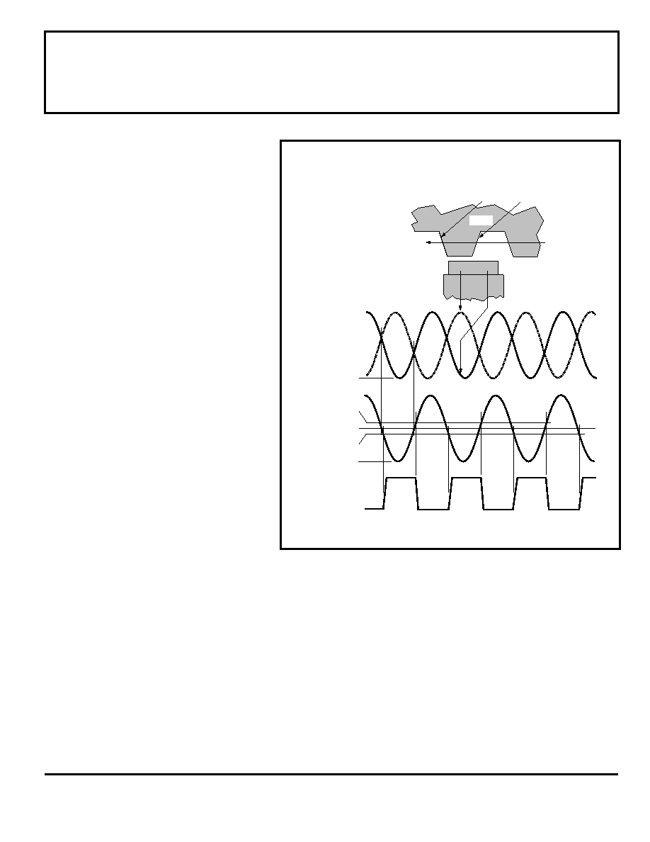
Figure 3 relates the output state of a
back-biased sensor IC, with switching
characteristics shown in Figure 2, to the
target gear profile and position. Assume a
north pole back-bias configuration (equivalent
to south pole at the face of the device). The
motion of the gear produces a phase-shifted
field at E1 and E2 (Figure 3 (a)); internal
conditioning circuitry subtracts the field at the
two elements (Figure 3 (b)); and the Schmitt
trigger at the output of the conditioning
circuitry switches at the pre-determined
thresholds (BOP and BRP). As shown (Figure
3 (c)), the IC output is LOW whenever element
E1 sees a (ferrous) gear tooth and element E2
faces air. The output is HIGH when element
E1 sees air and element E2 sees the ferrous
target.
A gear-tooth sensor IC can be configured
(see ASSEMBLY TECHNIQUES) to operate as a
latch, a (positive) switch, or a negative
switch. Note the change in duty cycle in
each of the cases (Figure 4).
A
latch is a device where the operate
point is greater than zero gauss and the
release point is less than zero gauss. With
the configuration shown in Figure 3, such a
device will switch ON on the leading edge
and OFF on the trailing edge of the target
tooth.
A
(positive) switch is a device where
both the operate and release points are
greater than zero gauss (positive values).
Figure 3
GEAR-TOOTH SENSOR IC OPERATION
OP
B = +25 G
B – B
E1
E2
GEAR
4300 G
4130 G
150 G
0 G
-150 G
RP
B = –25 G
V
OUT(SAT)
V
OUT
B & B
E1
E2
OUTPUT DUTY CYCLE ≈ 50%
Dwg. WH-003
DIRECTION
OF ROTATION
LEADING
EDGE
TRAILING
EDGE
NORTH
SOUTH
E2
E1
(a)
(b)
(c)
In the configuration shown in Figure 3, such a device will switch ON
and then switch OFF on the leading or rising edge of the target tooth
(Figure 4 (a)).
A
negative switch is a device where both the operate and release
points are less than zero gauss (negative values). In the configuration
shown in Figure 3, such a device will switch OFF and then switch ON
on the trailing or falling edge of the target tooth (Figure 4 (b)).
Speed sensor ICs can use any of the three configurations
described. Timing sensor ICs, however, must use a latch to guarantee
dual-edge detection. Latches are most easily made using the
A3058EU or A3058LU device types.
相關(guān)PDF資料 |
PDF描述 |
|---|---|
| A3064LKA-TL | MAGNETIC FIELD SENSOR-HALL EFFECT, 1.25-2.75mT, 0.14-0.40V, RECTANGULAR, THROUGH HOLE MOUNT |
| A3064LKA | MAGNETIC FIELD SENSOR-HALL EFFECT, 1.25-2.75mT, 0.14-0.40V, RECTANGULAR, THROUGH HOLE MOUNT |
| A31-1 | 10 MHz - 2000 MHz RF/MICROWAVE WIDE BAND LOW POWER AMPLIFIER |
| A32-1 | 100 MHz - 2000 MHz RF/MICROWAVE WIDE BAND LOW POWER AMPLIFIER |
| A3340LLHLT-T | MAGNETIC FIELD SENSOR-HALL EFFECT, 0.5-5mT, 270-500mV, RECTANGULAR, SURFACE MOUNT |
相關(guān)代理商/技術(shù)參數(shù) |
參數(shù)描述 |
|---|---|
| A3056LU | 制造商:ALLEGRO 制造商全稱:Allegro MicroSystems 功能描述:HALL EFFECT GEAR-TOOTH SENSORS ZERO SPEED |
| A3058EU | 制造商:ALLEGRO 制造商全稱:Allegro MicroSystems 功能描述:HALL EFFECT GEAR-TOOTH SENSORS ZERO SPEED |
| A3058LU | 制造商:ALLEGRO 制造商全稱:Allegro MicroSystems 功能描述:HALL EFFECT GEAR-TOOTH SENSORS ZERO SPEED |
| A3059 | 制造商:ALLEGRO 制造商全稱:Allegro MicroSystems 功能描述:HALL-EFFECT GEAR-TOOTH SENSORS -ACCOUPLED |
| A305ERU | 制造商:MPD 制造商全稱:MicroPower Direct, LLC 功能描述:Low Cost, 4:1 Input 3W Single & Dual Output DC/DC Converters |
發(fā)布緊急采購,3分鐘左右您將得到回復(fù)。