- 您現(xiàn)在的位置:買賣IC網(wǎng) > PDF目錄36481 > 95-132I25-P (ARIES ELECTRONICS INC) QFP132-PGA132, IC SOCKET PDF資料下載
參數(shù)資料
| 型號: | 95-132I25-P |
| 廠商: | ARIES ELECTRONICS INC |
| 元件分類: | 插座 |
| 英文描述: | QFP132-PGA132, IC SOCKET |
| 文件頁數(shù): | 1/1頁 |
| 文件大?。?/td> | 224K |
| 代理商: | 95-132I25-P |
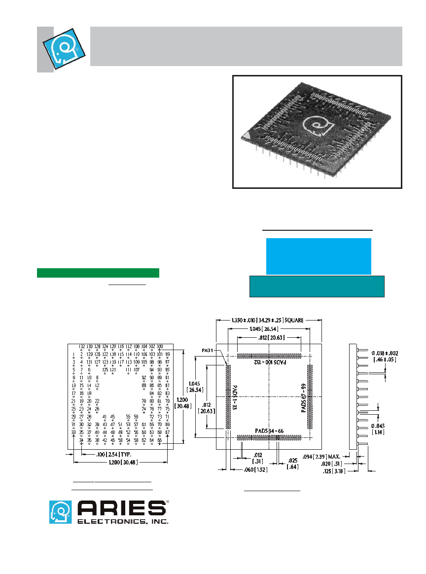
Part No. 95-132I25 - QFP to PGA Adapter
for JEDEC 132 Position, .025 [.64] Pitch
Note: Aries specializes in custom design and production. In addition to the
standard products shown on this page, special materials, platings, sizes, and
configurations can be furnished, depending on quantities. Aries reserves the
right to change product specifications without notice.
FEATURES:
Convert surface mount QFP packages to a 13 x 13 PGA
footprint.
Reduce costs by using less expensive QFP packages to
replace PGA footprints in existing designs.
Pins are mechanically fastened and soldered to board
using Aries’ patented process, creating a reliable electrical
connection and rugged contact.
Consult factory for panelized form or for mounting of con-
signed chips.
SPECIFICATIONS:
Adapter body is FR-4 with 1 ounce minimum Copper
traces.
Pads are bare Copper protected with Entek
by Enthone or
immersion white tin to eliminate coplanarity concerns and
solder bridges associated with hot air solder leveling.
Pins are Brass Alloy 360 1/2 hard per UNS C36000
ASTM-B16-00.
Pin plating is 200
μ [5.08μm] min. Tin per ASTM B 545 Type
1 or Tin/Lead 93/7 per ASTM B 545 over 100
μ [2.54μm]
Nickel per SAE-AMS-QQ-N-290.
Operating temperature=221°F [105°C].
MOUNTING CONSIDERATIONS:
Suggested PCB hole size=.028 ± .003 [.71 ± .08] dia.
Will plug into standard PGA sockets.
ORDERING INFORMATION
Tolerances:
Row-to-row:
± .003 [± .08]
Pin-to-pin:
± .003 [± .08] non-cumulative
All others:
± .005 [.13] unless otherwise specified
Specify Part No. 95-132I25
-or-
95-132I25-P for panelized form
when ordering
X-RAY VIEW TOP SIDE
QFP PAD ASSIGNMENT
TOP (QFP) SIDE
ALL DIMENSIONS: INCHES [MILLIMETERS]
Specify Part Number 132-PGM13072-30
for wire wrap PGA socket
PRINTOUTS OF THIS DOCUMENT MAY BE OUT OF DATE AND SHOULD BE CONSIDERED UNCONTROLLED
18017
REV.G
Frenchtown, NJ USA
TEL:
(908) 996-6841
FAX:
(908) 996-3891
http://www.arieselec.com info@arieselec.com
abc
相關(guān)PDF資料 |
PDF描述 |
|---|---|
| 95-200-08-BP3B | 125 um, SINGLE MODE, SIMPLEX SC CONNECTOR |
| 95-200-08-BP3G | 125 um, SINGLE MODE, SIMPLEX SC CONNECTOR |
| 95-200-08-BP3N | 125 um, SINGLE MODE, SIMPLEX SC CONNECTOR |
| 95-200-08-BP3R | 125 um, SINGLE MODE, SIMPLEX SC CONNECTOR |
| 95-200-08-BP3W | 125 um, SINGLE MODE, SIMPLEX SC CONNECTOR |
相關(guān)代理商/技術(shù)參數(shù) |
參數(shù)描述 |
|---|---|
| 95133 | 功能描述:防靜電控制產(chǎn)品 Adjustable Gray 7mm RoHS:否 制造商:3M Electronic Specialty 產(chǎn)品:Air Ionizers 類型:Mini 顏色: 大小:4.5 in x 3.3 in x 2 in |
| 951330-3 | 制造商: 功能描述: 制造商:undefined 功能描述: |
| 9513320000 | 制造商:Weidmuller 功能描述:TB10, M/PLATE, SS -EA - Bulk |
| 9513330000 | 制造商:Weidmuller 功能描述:TB11, M/PLATE, SS -EA - Bulk |
| 9513340000 | 制造商:Weidmuller 功能描述:MP NEXT 45/38 SS -EA - Bulk 制造商:Weidmuller 功能描述:MOUNTING PLATE MP NEXT 45/38 SS |
發(fā)布緊急采購,3分鐘左右您將得到回復(fù)。