- 您現(xiàn)在的位置:買(mǎi)賣(mài)IC網(wǎng) > PDF目錄36330 > 935077580157 (NXP SEMICONDUCTORS) SPECIALTY CONSUMER CIRCUIT, PQFP80 PDF資料下載
參數(shù)資料
| 型號(hào): | 935077580157 |
| 廠商: | NXP SEMICONDUCTORS |
| 元件分類(lèi): | 消費(fèi)家電 |
| 英文描述: | SPECIALTY CONSUMER CIRCUIT, PQFP80 |
| 封裝: | PLASTIC, SOT-318, QFP-80 |
| 文件頁(yè)數(shù): | 11/30頁(yè) |
| 文件大小: | 230K |
| 代理商: | 935077580157 |
第1頁(yè)第2頁(yè)第3頁(yè)第4頁(yè)第5頁(yè)第6頁(yè)第7頁(yè)第8頁(yè)第9頁(yè)第10頁(yè)當(dāng)前第11頁(yè)第12頁(yè)第13頁(yè)第14頁(yè)第15頁(yè)第16頁(yè)第17頁(yè)第18頁(yè)第19頁(yè)第20頁(yè)第21頁(yè)第22頁(yè)第23頁(yè)第24頁(yè)第25頁(yè)第26頁(yè)第27頁(yè)第28頁(yè)第29頁(yè)第30頁(yè)
1996 Oct 25
19
Philips Semiconductors
Preliminary specication
Progressive scan-Zoom and Noise
reduction IC (PROZONIC)
SAA4990H
Microcontroller interface (SNERT)
In the microcontroller interface the external signals SNDA
and SNCL are processed to address and data. Data
enable pulses are derived from the received addresses.
The data enable pulses are used elsewhere for input
enabling the delivered data into various control registers.
The microcontroller interface operates in a few stages:
1. SNCL positive and negative edges are sampled
2. on each negative edge of SNCL and SNDA data is
shifted in a shift register
3. starting from phase 0, a counter counts positive edges
of SNCL
4. during phase 7, but waited for a negative edge of
SNCL, so after the 8th negative edge of SNCL, an
address latch enable pulse is made, whereby the shift
register contents are taken over in the address register
5. in the address range 10H to 27H, the addresses are
decoded in two steps
6. during phase 15, but waited for a negative edge of
SNCL, so after the 16th negative edge of SNCL, the
address has been decoded and will be passed to any
of the data enable pulses.
For each of the functions vert_start_box and
vert_stop_box, two addresses are used, in which the LSB
from the address is taken as an extra MSB for the data.
This is done because vert_start_box and vert_stop_box
must be supplied with 9-bit data. All other data from the
SNERT-bus has only relevance in the 7:0 range.
During the data phases (phase 8 to 15), each negative
edge produces a shift pulse for the movie phase detect
circuit that produces output data on the SNDA signal. The
data enables for the movie phase detect circuit are active
in all of the data phases, when an address 26 or 27 has
been decoded.
After an MPD read transmission it is necessary to send a
second (dummy) transmission to the PROZONIC.
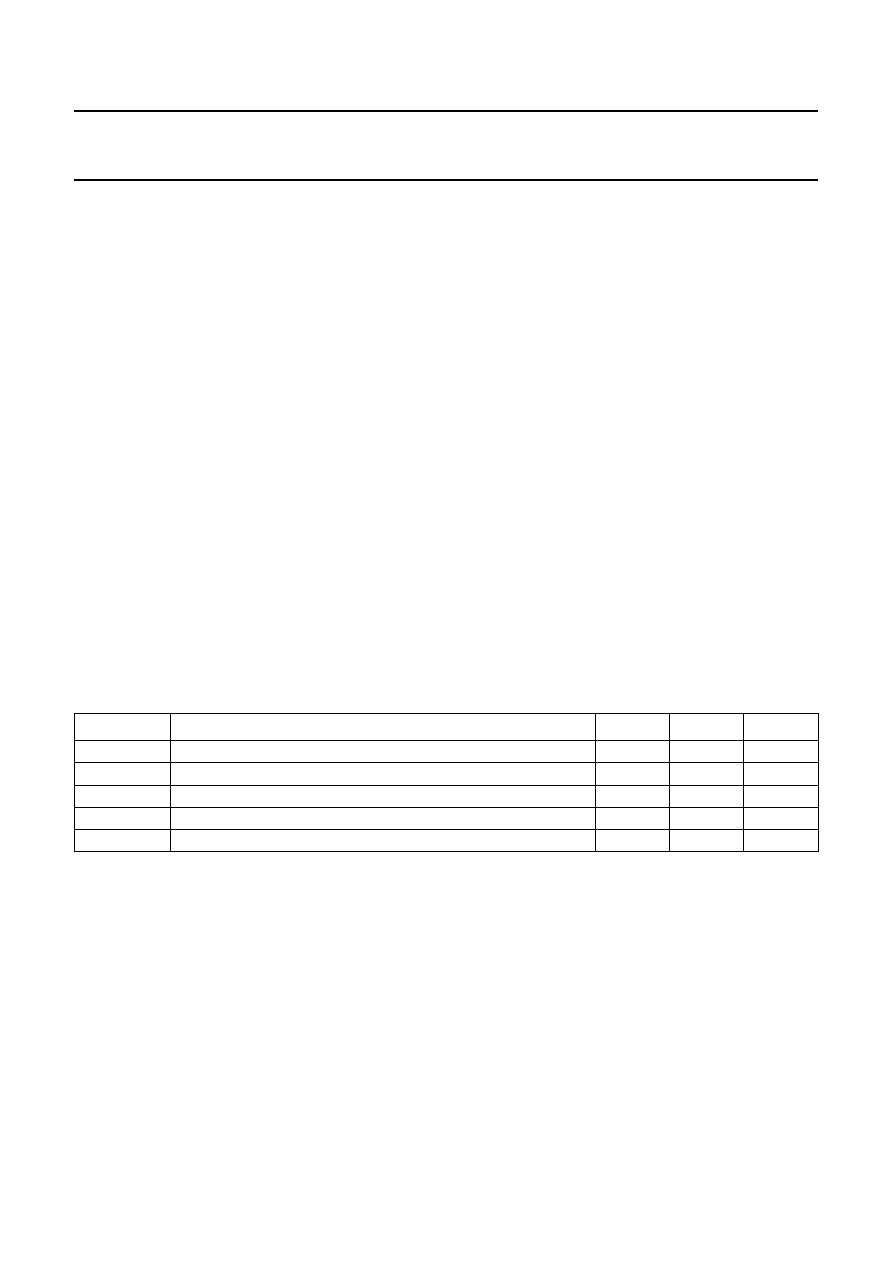
LIMITING VALUES
In accordance with the Absolute Maximum Rating System (IEC 134).
SYMBOL
PARAMETER
MIN.
MAX.
UNIT
VI
input voltage
0.5
+7
V
VDDD
digital supply voltage
0.5
+7
V
VDDA
analog supply voltage
0.5
+7
V
Tstg
storage temperature
65
+150
°C
Tamb
operating ambient temperature
0
70
°C
相關(guān)PDF資料 |
PDF描述 |
|---|---|
| 935206750518 | SPECIALTY CONSUMER CIRCUIT, PQFP80 |
| 935206750557 | SPECIALTY CONSUMER CIRCUIT, PQFP80 |
| 935075380112 | SPECIALTY CONSUMER CIRCUIT, PDSO28 |
| 935075380118 | SPECIALTY CONSUMER CIRCUIT, PDSO28 |
| 935080330112 | 1-CH 8-BIT PROPRIETARY METHOD ADC, PARALLEL ACCESS, PDSO24 |
相關(guān)代理商/技術(shù)參數(shù) |
參數(shù)描述 |
|---|---|
| 935079-000 | 制造商:TE Connectivity 功能描述:55A1841-16-MST4-9CS2275 - Cable Rools/Shrink Tubing |
| 935087-000 | 制造商:TE Connectivity 功能描述:301A511-51-05/164-0 - Bulk |
| 935087N001 | 制造商:TE Connectivity 功能描述:301A511-51-05/164-CS7092 制造商:TE Connectivity 功能描述:301A511-51-05/164-CS7092 - Bulk |
| 9350DC-200-0GZZZA | 制造商:Siemens 功能描述: |
| 9350DC-200-0ZZZTA | 制造商:Siemens 功能描述: |
發(fā)布緊急采購(gòu),3分鐘左右您將得到回復(fù)。