- 您現(xiàn)在的位置:買(mǎi)賣(mài)IC網(wǎng) > PDF目錄366259 > 80C03 Digital Temperature Sensor with SPI™ Interface, -55C to +125C, 8-MSOP, T/R PDF資料下載
參數(shù)資料
| 型號(hào): | 80C03 |
| 元件分類(lèi): | 溫度/濕度傳感器 |
| 英文描述: | Digital Temperature Sensor with SPI™ Interface, -55C to +125C, 8-MSOP, T/R |
| 中文描述: | 80C03 AutoDUPLEX的CMOS以太網(wǎng)數(shù)據(jù)鏈路控制器手冊(cè)9 / 96 |
| 文件頁(yè)數(shù): | 3/19頁(yè) |
| 文件大小: | 247K |
| 代理商: | 80C03 |
第1頁(yè)第2頁(yè)當(dāng)前第3頁(yè)第4頁(yè)第5頁(yè)第6頁(yè)第7頁(yè)第8頁(yè)第9頁(yè)第10頁(yè)第11頁(yè)第12頁(yè)第13頁(yè)第14頁(yè)第15頁(yè)第16頁(yè)第17頁(yè)第18頁(yè)第19頁(yè)
80C03
4-3
MD400121/C
FIRST BYTE
LAST BYTE
DESTINATION
ADDRESS
(6 BYTES)
SOURCE
ADDRESS
(6 BYTES)
BYTE COUNT
(2 BYTES)
DATA
(46 – 1500
BYTES)
A7
A15
A23
A31
A39
A47
B7
B15
B23
B31
B39
B47
T7
T15
D7
A0
A8
A16
A24
A32
A40
B0
B8
B16
B24
B32
B40
T0
T8
D0
. . . . . .
. . . . . .
. . . . . .
. . . . . .
. . . . . .
. . . . . .
. . . . . .
. . . . . .
. . . . . .
. . . . . .
. . . . . .
. . . . . .
. . . . . .
. . . . . .
. . . . . .
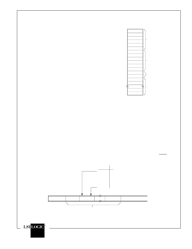
Figure 3. Typical Frame Buffer Format for
Byte-Organized Memory
EDLC chip encapsulates these fields into an Ethernet
frame by inserting a preamble prior to these information
fields and appending a CRC after the information fields.
The chip can be programmed to exclude inclusion of the
preamble and/or he FCS rom he ransmit data stream. In
this case it is assumed that the preamble and FCS are
provided as part of the data written to the chip.
Transmission Initiation/Deferral
The Ethernet node initiates a transmission by storing the
entire nformation content of the frame to be transmitted n
an external buffer memory, and then transferring initial
frame bytes to the EDLC Transmit FIFO. “Transmit-buffer
to FIFO” transfers are coordinated via the TxWR and
TxRDY handshake interface, i.e., bytes are written to the
BIT
NAME
RxTxD0
RxTxD1
RxTxD2
RxTxD3
RxTxD4
RxTxD5
RxTxD6
RxTxD7
PIN
NO.
6
7
8
9
10
11
12
13
PREAMBLE
FIRST BYTE
SIXTH BYTE
A0 . . . A7
A8 . . . A15
. . . . . .
A40 . . . A47
SOURCE ADDRESS . . .
DESTINATION ADDRESS
BITS WITHIN A BYTE TRANSMITTED/RECEIVED BIT NO. "0" FIRST THROUGH BIT NO. "7" LAST.
. . .
Preamble:
The preamble is a 64-bit field consisting of 62
alternating “1”s and “0”s followed by a “11” End-of-Pre-
amble indicator.
Destination Address:
The Destination Address is a 6-
byte field containing either a specific Station Address, a
Broadcast Address, or a Multicast Address to which this
frame is directed.
Source Address:
The Source Address is a 6-byte field
containing the specific Station Address from which this
frame originated.
Byte-Count Field:
The Byte-Count Field consists of two
bytes providing the number of valid data bytes in the Data
Field, 46 to 1500. This field is uninterpreted at the Data
Link Layer, and is passed through the EDLC chip to be
handled at the Client Layer.
Data Field:
The Data Field consists of 46 to 1500 bytes of
information which are fully transparent in the sense that
any arbitrary sequence of bytes may occur.
Frame Check Sequence:
The Frame Check Sequence
(FCS) field is a 32-bit cyclic redundancy check (CRC)
value computed as a function of the Destination Address
Field, Source Address Field, Type Field and Data Field.
The FCS s appended o each ransmitted rame, and used
at reception to determine if the received frame is valid.
Transmitting
The transmit data stream consists of the Preamble, four
information fields, and the FCS which is computed in real
time by the EDLC chip and automatically appended to the
frame at the end of the serial data. The Preamble is also
generated by the EDLC chip and transmitted immediately
prior to the Destination Address. Destination Address,
Source Address, Type Field and Data Field are prepared
in the buffer memory prior to initiating transmission. The
Figure 4. Bit Serialization/Deserialization
相關(guān)PDF資料 |
PDF描述 |
|---|---|
| 80C03 | AutoDUPLEX CMOS Ethernet Data Link Controller(AutoDUPLEX CMOS 以太網(wǎng)數(shù)據(jù)鏈路控制器) |
| 80C154S | Digital Temperature Sensor with SPI™ Interface, -55C to +125C, 8-DFN, T/R |
| 83C154S | CMOS 8-bit Microcontroller(258.00 k) |
| 81400000 | LACING CORD 25M RL |
| 81451 | BECHERKLEMME T2123 |
相關(guān)代理商/技術(shù)參數(shù) |
參數(shù)描述 |
|---|---|
| 80C07B | 制造商:未知廠家 制造商全稱(chēng):未知廠家 功能描述:OPTICAL SAMPLING MODULES |
| 80C08C | 制造商:未知廠家 制造商全稱(chēng):未知廠家 功能描述:OPTICAL SAMPLING MODULES |
| 80C151SB | 制造商:INTEL 制造商全稱(chēng):Intel Corporation 功能描述:HIGH-PERFORMANCE CHMOS MICROCONTROLLER |
| 80C152 | 制造商:Intel 功能描述: |
| 80C152JA | 制造商:INTEL 制造商全稱(chēng):Intel Corporation 功能描述:UNIVERSAL COMMUNICATION CONTROLLER 8-BIT MICROCONTROLLER |
發(fā)布緊急采購(gòu),3分鐘左右您將得到回復(fù)。