- 您現(xiàn)在的位置:買賣IC網(wǎng) > PDF目錄252163 > 805J1000562MXBE03 (SYFER TECHNOLOGY LTD) 1 FUNCTIONS, 100 V, FEED THROUGH CAPACITOR PDF資料下載
參數(shù)資料
| 型號(hào): | 805J1000562MXBE03 |
| 廠商: | SYFER TECHNOLOGY LTD |
| 元件分類: | 數(shù)據(jù)傳輸濾波器 |
| 英文描述: | 1 FUNCTIONS, 100 V, FEED THROUGH CAPACITOR |
| 封裝: | EIA STD PACKAGE SIZE 0603, CERAMIC PACKAGE-3 |
| 文件頁數(shù): | 1/4頁 |
| 文件大?。?/td> | 194K |
| 代理商: | 805J1000562MXBE03 |
notes
1. For details of ordering see page 62
2. For soldering and installation information see page 69
* The 0603 chip size is a development item that will be available during the life
of this catalogue. All technical information should be considered provisional
and subject to change.
Integrated Passive Components
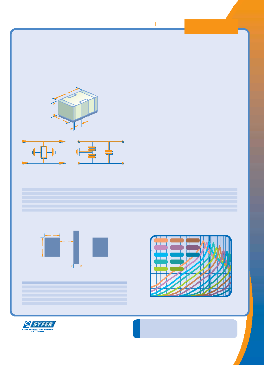
Balanced Line EMI Chip
BLC
The Syfer Balanced Line Chip is a 3 terminal EMI chip device. The
revolutionary design provides simultaneous line-to-line and line-to-
ground filtering, using a single ceramic chip. In this way, differential
and common mode filtering are provided in one device. Capable of
replacing 2 or more conventional devices, it is ideal for balanced lines,
twisted pairs and dc motors, in automotive, audio, sensor and other
applications.
These filters can prove invaluable in meeting stringent EMC demands
particularly in automotive applications.
Specifications
W
T
L2
L
L1
Chip
Size
L
W
T
L1
L2
0603*
1.6±0.2 (0.063±0.008)
0.8±0.2 (0.03±0.008)
0.5±0.15 (0.02±0.006)
0.3±0.2 (0.012±0.008)
0.2±0.1 (0.008±0.004)
0805
2.0±0.3 (0.08±0.012)
1.25±0.2 (0.05±0.008)
1.0±0.15 (0.04±0.006)
0.5±0.25 (0.02±0.01)
0.3±0.15 (0.012±0.006)
1206
3.2±0.3 (0.126±0.012)
1.60±0.2 (0.063±0.008)
1.1±0.2 (0.43±0.008)
0.95±0.3 (0.037±0.012)
0.5±0.25 (0.02±0.01)
1410
3.6±0.3 (0.14±0.012)
2.5±0.3 (0.1±0.012)
2 max. (0.08 max.)
1.20±0.3 (0.047±0.012)
0.5±0.25 (0.02±0.01)
1812
4.5±0.35 (0.18±0.14)
3.2±0.3 (0.126±0.012)
2 max. (0.08 max.)
1.5±0.35 (0.6±0.14)
0.5±0.25 (0.02±0.01)
2220
5.7±0.4 (0.22±0.016)
5.0±0.4 (0.2±0.016)
2.5 max. (0.1 max.)
2.25±0.4 (0.09±0.016)
0.75±0.25 (0.03±0.01)
Dielectric
X7R or C0G
Electrical Configuration
Multiple capacitance
Capacitance Measurement
At 1000hr point
Typical Capacitance Matching Better than 5%
Temperature Rating
-55°C to 125°C
Dielectric Withstand Volage
2.5 x Rated Volts for 5 secs.
Charging current limited to 50mA Max.
Insulation Resistance
10,000 Mohms Min
Termination Material
Nickel Barrier
Advantages
● Replaces 2 or 3 capacitors with one device
● Matched capacitance line to ground on both lines
● Low inductance due to cancellation effect
● Capacitance line to line
● Differential and common mode attenuation
● Effects of temperature and voltage variation eliminated
● Effect of ageing equal on both lines
● High current capability
Applications
● Balanced lines
● Twisted pairs
● EMI Suppression on DC motors
● Sensor/transducer applications
● Wireless communications
● Audio
GROUND
AA
BB
C1
C2
INPUT 1
INPUT 2
A
B
D
C
Recommended Solder Lands
220nF
100nF
47nF
22nF
10nF
4.7nF
2.2nF
1nF
470pF
220pF
100pF
47pF
22pF
0
20
40
60
80
0.1
1
10
100
1000
Insertion Loss Characteristics (common mode)
Typical 50 ohm system
Insertion
Loss
(dB)
Frequency (MHz)
Dimensions mm (inches)
Chip Size
A
B
C
D
0603* 0.6 (0.024) 0.6 (0.024)
0.4 (0.016)
0.2 (0.008)
0805
0.95 (0.037) 0.9 (0.035)
0.3 (0.012)
0.4 (0.016)
1206
1.2 (0.047) 0.9 (0.035)
0.6 (0.024)
0.8 (0.03)
1410
2.05 (0.08)
1.0 (0.04)
0.7 (0.028)
0.9 (0.035)
1812
2.65 (0.104) 1.4 (0.055)
0.8 (0.03)
1.4 (0.055)
2220
4.15 (0.163) 1.4 (0.055)
1.2 (0.047)
1.8 (0.071)
59
相關(guān)PDF資料 |
PDF描述 |
|---|---|
| 805J1000562MXRE03 | 1 FUNCTIONS, 100 V, FEED THROUGH CAPACITOR |
| 805J1000562MXTE03 | 1 FUNCTIONS, 100 V, FEED THROUGH CAPACITOR |
| 805J1000680MCBE03 | 1 FUNCTIONS, 100 V, FEED THROUGH CAPACITOR |
| 805J1000680MCRE03 | 1 FUNCTIONS, 100 V, FEED THROUGH CAPACITOR |
| 805J1000680MCTE03 | 1 FUNCTIONS, 100 V, FEED THROUGH CAPACITOR |
相關(guān)代理商/技術(shù)參數(shù) |
參數(shù)描述 |
|---|---|
| 805J160 | 制造商:Ohmite Mfg Co 功能描述: |
| 805J1K0E | 制造商:OHMITE 制造商全稱:Ohmite Mfg. Co. 功能描述:Metal-Mite? Aluminum Housed Axial Term. Wirewound, 1% Tolerance |
| 805J1K5E | 制造商:OHMITE 制造商全稱:Ohmite Mfg. Co. 功能描述:Metal-Mite? Aluminum Housed Axial Term. Wirewound, 1% Tolerance |
| 805J1R0E | 制造商:OHMITE 制造商全稱:Ohmite Mfg. Co. 功能描述:Metal-Mite? Aluminum Housed Axial Term. Wirewound, 1% Tolerance |
| 805J250E | 制造商:OHMITE 制造商全稱:Ohmite Mfg. Co. 功能描述:Metal-Mite? Aluminum Housed Axial Term. Wirewound, 1% Tolerance |
發(fā)布緊急采購(gòu),3分鐘左右您將得到回復(fù)。