- 您現(xiàn)在的位置:買賣IC網(wǎng) > PDF目錄360549 > 7P064ATA1003C25 Flash Memory Card(64M位閃速存儲(chǔ)器卡) PDF資料下載
參數(shù)資料
| 型號(hào): | 7P064ATA1003C25 |
| 英文描述: | Flash Memory Card(64M位閃速存儲(chǔ)器卡) |
| 中文描述: | 閃存卡(6400位閃速存儲(chǔ)器卡) |
| 文件頁(yè)數(shù): | 8/25頁(yè) |
| 文件大小: | 224K |
| 代理商: | 7P064ATA1003C25 |
第1頁(yè)第2頁(yè)第3頁(yè)第4頁(yè)第5頁(yè)第6頁(yè)第7頁(yè)當(dāng)前第8頁(yè)第9頁(yè)第10頁(yè)第11頁(yè)第12頁(yè)第13頁(yè)第14頁(yè)第15頁(yè)第16頁(yè)第17頁(yè)第18頁(yè)第19頁(yè)第20頁(yè)第21頁(yè)第22頁(yè)第23頁(yè)第24頁(yè)第25頁(yè)
June 2000 Rev. 5 - ECO #12901
8
PCMCIA Flash Memory Card
ATA10 Series
PC Card Products
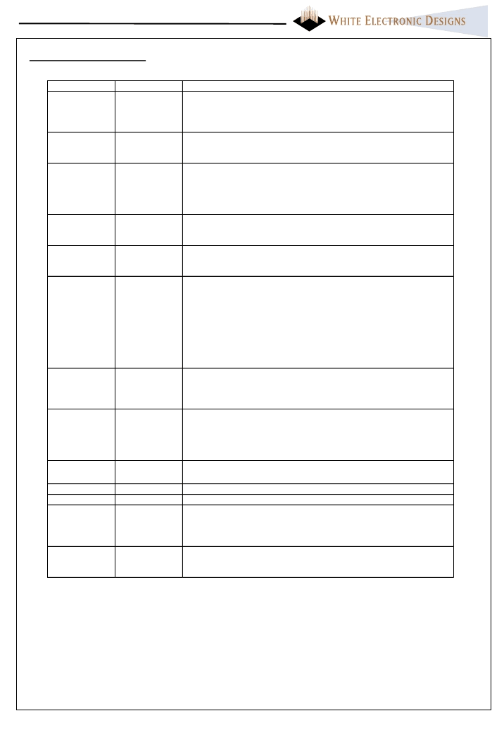
Symbol
A0 – A10
Type
Name and Function
INPUT
ADDRESS INPUTS:
A0 through A10 Signal A0 is not used in word
access mode. A10 is the most significant bit. In True IDE Mode only
HA[2..0] are used for selecting the eight registers in the Task File, the
remaining address lines should be grounded.
DATA INPUT/OUTPUT:
D0 THROUGH D15 constitute the bi-
directional databus. D0 - D7 constitute the lower (even) byte and D8 -
D15 the upper (odd) byte. D15 is the MSB.
CARD ENABLE 1 AND 2:
active low signals; CE1# enables even
byte accesses, CE2# enables odd byte accesses. In True IDE Mode
CE2# is used to select the Alternate Status Register and the Device
control Register while CE1# is the cheap select for the other task file
registers.
OUTPUT ENABLE, ATA Select:
Active low signal enabling read
data from Attribute and Common memory area. To enable True IDE
Mode this input should be grounded by the host.
WRIT E ENABLE:
Active low signal gating write data to the memory
card. In true IDE Mode this input signal is not used and should be
connected to Vcc.
Ready/Busy, Interrupt Request:
In I/O mode this signal is is
IREQ # pin. The signal of low level indicates that the card is requesting
software service to host, and high level indicate that the card is not
requesting. In memory mode, the signal is set high when the ATA card
is ready to accept new data transfer operation and held low when card
is busy.
At power up and at Reset, the RDY /BSY is low until (busy) until the
card has completed its power up or reset function.
Host should provide a pull up resistor
CARD DET ECT 1 and 2:
Provide card insertion detection. These
signals are connected to ground internally on the memory card. The
host socket interface circuitry shall supply 10K-ohm or larger pull-up
resistors on these signal pins.
Write Protect, 16 bit I/O port:
In memory mode, WP is held low:
always writable). In I/O mode , IOIS16# is asserted low when Task
File Registers are accessed in 16 bit mode. In True IDE mOde this
signal is asserted low when this device is expecting a word data transfer
cycle.
PROGRAM/ERASE POWER SUPPLY:
No Connection for ATA
card.
CARD POWER SUPPLY:
5.0V for all internal circuitry.
GROUND:
for all internal circuitry.
ATTRIBUT E MEMORY SEL ECT:
Used to enable access to
Attribute space. Should be in high level during common memory area
access. In True IDE Mode input signal is not used and should be
connected to Vcc.
Reset, Reset#:
Active signal will clear all registers on the card (power
on default). In True IDE Mode Reset# is the active low hardware reset
from the host.
D0 - D15
INPUT/OUT
PUT
CE1#, CE2#
INPUT
OE#,
ASTEL #
INPUT
WE#
INPUT
RDY /BSY #
IREQ #
INTRQ
OUTPUT
CD1#, CD2#
OUTPUT
WP
IOIS16#
OUTPUT
VPP1, VPP2
N.C.
VCC
GND
REG #
INPUT
Reset
Reset#
INPUT
Card Signal Description
相關(guān)PDF資料 |
PDF描述 |
|---|---|
| 7P192ATA1003C25 | Flash Memory Card(192M位閃速存儲(chǔ)器卡) |
| 7P256ATA1003C25 | Flash Memory Card(256M位閃速存儲(chǔ)器卡) |
| 7P008ATA1003C25 | Flash Memory Card(8M位閃速存儲(chǔ)器卡) |
| 7P016ATA1003C25 | Flash Memory Card(16M位閃速存儲(chǔ)器卡) |
| 7P032ATA1003C25 | Flash Memory Card(32M位閃速存儲(chǔ)器卡) |
相關(guān)代理商/技術(shù)參數(shù) |
參數(shù)描述 |
|---|---|
| 7P-10.000MBP-T | 功能描述:OSC TCXO 10.000MHZ CMOS SMD 制造商:txc corporation 系列:* 零件狀態(tài):在售 標(biāo)準(zhǔn)包裝:1,000 |
| 7P102V330A052 | 制造商:CDE 制造商全稱:Cornell Dubilier Electronics 功能描述:Type 7P 55 ∑C Photoflash, High-Energy, Long Life, Aluminum |
| 7P102V330N042 | 制造商:CDE 制造商全稱:Cornell Dubilier Electronics 功能描述:Type 7P 55 ∑C Photoflash, High-Energy, Long Life, Aluminum |
| 7P102V360A052 | 功能描述:鋁質(zhì)電解電容器-管理單元 1000uF 360V PHOTO RoHS:否 制造商:Nichicon 電容:470 uF 容差:20 % 電壓額定值:450 V ESR: 工作溫度范圍:- 25 C to + 105 C 系列:AR 直徑:35 mm 長(zhǎng)度:45 mm 引線間隔:10 mm 產(chǎn)品:General Purpose Electrolytic Capacitors |
| 7P122V330A052 | 制造商:CDE 制造商全稱:Cornell Dubilier Electronics 功能描述:Type 7P 55 ∑C Photoflash, High-Energy, Long Life, Aluminum |
發(fā)布緊急采購(gòu),3分鐘左右您將得到回復(fù)。