- 您現(xiàn)在的位置:買賣IC網(wǎng) > PDF目錄369352 > 795R (意法半導(dǎo)體) 3V Supervisor with Battery Switchover PDF資料下載
參數(shù)資料
| 型號(hào): | 795R |
| 廠商: | 意法半導(dǎo)體 |
| 英文描述: | 3V Supervisor with Battery Switchover |
| 中文描述: | 3V的監(jiān)控與電池切換 |
| 文件頁(yè)數(shù): | 6/32頁(yè) |
| 文件大?。?/td> | 304K |
| 代理商: | 795R |
第1頁(yè)第2頁(yè)第3頁(yè)第4頁(yè)第5頁(yè)當(dāng)前第6頁(yè)第7頁(yè)第8頁(yè)第9頁(yè)第10頁(yè)第11頁(yè)第12頁(yè)第13頁(yè)第14頁(yè)第15頁(yè)第16頁(yè)第17頁(yè)第18頁(yè)第19頁(yè)第20頁(yè)第21頁(yè)第22頁(yè)第23頁(yè)第24頁(yè)第25頁(yè)第26頁(yè)第27頁(yè)第28頁(yè)第29頁(yè)第30頁(yè)第31頁(yè)第32頁(yè)

STM690/704/795/802/804/805/806
6/32
Pin Descriptions
MR (Manual Reset).
A logic low on /MR asserts
the reset output. Reset remains asserted as long
as MR is low and for t
rec
after MR returns high.
This active-low input has an internal pull-up. It can
be driven from a TTL or CMOS logic line, or short-
ed to ground with a switch. Leave open if unused.
WDI (Watchdog Input).
If WDI remains high or
low for 1.6sec, the internal watchdog timer runs
out and reset is triggered. The internal watchdog
timer clears while reset is asserted or when WDI
sees a rising or falling edge.
The watchdog function cannot be disabled by al-
lowing the WDI pin to float.
RST (Active-low Reset).
Pulses low for t
rec
when triggered, and stays low whenever V
CC
is
below the reset threshold or when MR is a logic
low. It remains low for t
rec
after either V
CC
rises
above the reset threshold, the watchdog triggers a
reset, or MR goes from low to high.
RST (Active-high Reset - Open Drain).
Pulses
high for t
rec
when triggered, and stays high when-
ever V
CC
is above the reset threshold or when MR
is a logic high. It remains high for t
rec
after either
V
CC
falls below the reset threshold, the watchdog
triggers a reset, or MR goes from high to low.
PFI (Power-fail Input).
When PFI is less than
V
PFI
or when V
CC
falls below V
SW
(2.4V), PFO
goes low; otherwise, PFO remains high. Connect
to ground if unused.
PFO (Power-fail Output).
When PFI is less than
V
PFI
, or V
CC
falls below V
SW
, PFO goes low; oth-
erwise, PFO remains high. Leave open if unused.
V
OUT
(Supply Output Voltage).
When V
CC
is
above the switchover voltage (V
SO
), V
OUT
is con-
nected to V
CC
through a P-channel MOSFET
switch. When V
CC
falls below V
SO
, V
BAT
connects
to V
OUT
. Connect to V
CC
if no battery is used.
Vccsw (V
CC
Switch Output).
When
switches to battery, Vccsw is high. When V
OUT
switches back to V
CC
, Vccsw is low. It can be used
to drive gate of external PMOS transistor for I
OUT
requirements exceeding 75mA.
V
OUT
E (Chip Enable Input).
The input to the chip-en-
able gating circuit. Connect to ground if unused.
E
CON
(Conditional Chip Enable).
E
CON
low only when E is low and reset is not asserted. If
E
CON
is low when reset is asserted, E
CON
will re-
main low for 15μs or until E goes high, whichever
occurs first. In the disabled mode, E
CON
is pulled
up to V
OUT
.
goes
V
BAT
(Back-up Battery Input).
When V
CC
falls
below V
SO
, V
OUT
switches from V
CC
to V
BAT
.
When V
CC
rises above V
SO
+ hysteresis, V
OUT
re-
connects to V
CC
. V
BAT
may exceed V
CC
. Connect
to V
CC
if no battery is used.
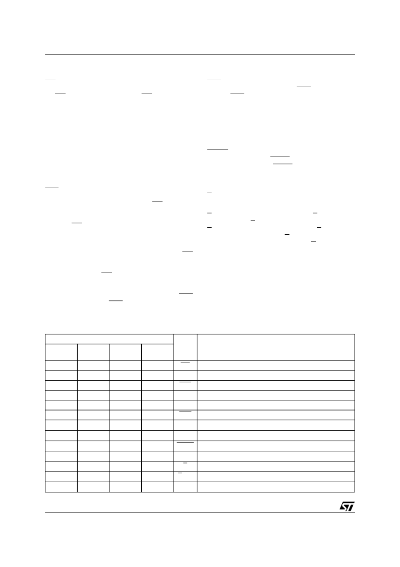
Table 3. Pin Description
Pin
Name
Function
STM795
STM690
STM802
STM704
STM806
STM804
STM805
–
–
6
–
MR
Push-button Reset Input
–
6
–
6
WDI
Watchdog Input
7
7
7
–
RST
Active-Low Reset Output
–
–
–
7
RST
Active-High Reset Output
–
4
4
4
PFI
Power-fail Input
–
5
5
5
PFO
Power-fail Output
1
1
1
1
V
OUT
Supply Output for External LPSRAM
2
2
2
2
V
CC
Supply Voltage
3
–
–
–
Vccsw
V
CC
Switch Output
4
3
3
3
V
SS
Ground
5
–
–
–
E
Chip Enable Input
6
–
–
–
E
CON
Conditioned Chip Enable Output
8
8
8
8
V
BAT
Backup-Battery Input
相關(guān)PDF資料 |
PDF描述 |
|---|---|
| 795S | 3V Supervisor with Battery Switchover |
| 795T | 3V Supervisor with Battery Switchover |
| 79600A | Three-Terminal Low Current Negative Voltage Regulators |
| 79L08AC | Three-Terminal Low Current Negative Voltage Regulators |
| 79L08ACD | Three-Terminal Low Current Negative Voltage Regulators |
相關(guān)代理商/技術(shù)參數(shù) |
參數(shù)描述 |
|---|---|
| 795S | 制造商:STMICROELECTRONICS 制造商全稱:STMicroelectronics 功能描述:3V Supervisor with Battery Switchover |
| 795T | 制造商:STMICROELECTRONICS 制造商全稱:STMicroelectronics 功能描述:3V Supervisor with Battery Switchover |
| 795XFL-2 CAL | 制造商:Starrett Company 功能描述:CALIBRATED - 1-2" 25-50MM ELECTRONIC MICROMETER WITH OUTPUT |
| 795XFL-2 CAL DU | 制造商:Starrett Company 功能描述:CALIBRATED W/ DATA & UNCERTAINTIES - 1-2" 25-50MM ELECTRONIC MICROMETER WITH OUT |
| 796 | 功能描述:電路板硬件 - PCB NYL Rd Clr Hle Spcr 1.00 .312OD #10 RoHS:否 制造商:Harwin 類型:Shield Clip 長(zhǎng)度:9.4 mm 螺紋大小: 外徑: 材料:Beryllium Copper 電鍍:Tin |
發(fā)布緊急采購(gòu),3分鐘左右您將得到回復(fù)。