- 您現(xiàn)在的位置:買賣IC網(wǎng) > PDF目錄360543 > 7906H-1-000 1.8V, 200kHz single low-cost, CMOS Op Amplifier on 120K Analog ROM process., -40C to +125C, 5-SOT-23, T/R PDF資料下載
參數(shù)資料
| 型號: | 7906H-1-000 |
| 英文描述: | 1.8V, 200kHz single low-cost, CMOS Op Amplifier on 120K Analog ROM process., -40C to +125C, 5-SOT-23, T/R |
| 中文描述: | LEITERPLATTENTASTER毫米5ST |
| 文件頁數(shù): | 36/37頁 |
| 文件大小: | 1915K |
| 代理商: | 7906H-1-000 |
第1頁第2頁第3頁第4頁第5頁第6頁第7頁第8頁第9頁第10頁第11頁第12頁第13頁第14頁第15頁第16頁第17頁第18頁第19頁第20頁第21頁第22頁第23頁第24頁第25頁第26頁第27頁第28頁第29頁第30頁第31頁第32頁第33頁第34頁第35頁當(dāng)前第36頁第37頁
Specifications are subject to change without notice.
374
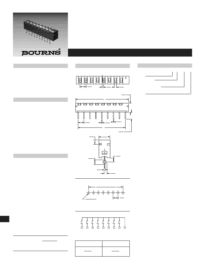
SPI Series Single In Line Package Switch
Features
I
Double contact offers high reliability
I
Splay teminals for automatic insertion by
IC machine
I
Insert molding of terminals and
ultrasonic welding
I
High density and thinner outline to
reduce package space
Applications
I
Interface boards from PC to modems,
printers, plotters, instruments for IBM
I
PC/XT/AT and compatibles
I
Portable data logging systems
I
Auto dialing & alarm monitoring systems
I
I/O modules, signal conditioners
I
Converters (communication)
SPI X - 8 - X
Model
Terminal Style
X = Straight
Number of positions
8 = 8 positions (9 pins)
Option
X = Standard packaging (tube)
DIMENSIONS ARE:
METRIC
(INCHES)
TOLERANCES: ±.2 EXCEPT WHERE NOTED.
Product Dimensions
Electrical Characteristics
Electrical Life ..........1,000 operation cycles
per switch min.
Non-Switching Rating ........100mA, 50VDC
Switching Rating ....................10mA, 5VDC
Contact Resistance ..........100mohms max.
Insulation Resistance ........100Mohms min.
DC 100V min.
Dielectric Strength ....AC 300V for 1 minute
Capacitance..................................5pF max.
Circuit ....................Single pole single throw
Environmental Characteristics
Mechanical Life....................1,000 operations
per switch min.
Operation Force..........................800g max.
Operating Temp. Range......-30°C to +80°C
Storage Temperature..........-30°C to +80°C
Vibration Test......................MIL-STD-202F,
Method 201A
Frequency ..............10-50-10 Hz/1 minute
Directions ................X,Y,Z, three mutually
perpendicular directions
Time......................2 hours each direction,
high reliability
Shock Test ..........................MIL-STD-202F,
Method 213B, Condition A
Gravity ............50G (peak value), 11 msec
Direction & Times....................6 sides and
3 times in each direction,
high reliability
Physical Characteristics
Cover Materials ....................Thermoplastic
PBT, UL94V-0; black
Base Materials ......................Thermoplastic
PPS, UL94V-0; black
Actuator Materials ................Thermoplastic
Nylon, UL94V-0; white
Contact Materials..Alloy Copper C5210-EH
Contact Plating ............3 Micro inches gold
over 40 micro inches nickel
Terminal Materials ............Brass C2680C-H
with 90/10 solder
Hand Soldering Process ....Use a soldering
iron of 30 watts or less,
controlled at 270°C (608°F) for
approx. 3 sec. while applying
solder
Wave Soldering ........Recommended solder
at 245° C. 5 sec.
Cleaning Process..........Freon TF or TE give
excellent results. When vapor
methods are used, do not subject the
switch to solvents at temperatures
above 51°C (125°F).
Packaging ............................All poles in the
“off” position
How to Order
SPIX
A
0.50
(.020)
3.60
(.142)
5.00
(.197)
RECOMMENDED PCB LAYOUT
B
±
0.10 = 2.54 x (P-1)
(B
±
.004 = .100 x (P-1)
0.97
±
.002) DIA.
(.038
±
ON
8
7
6
5
4
3
(2.54
2
1
C
0.90
(.035)
B
0.60
(.024)
(2.54
0.40
(.016)
(2.54
3.20
(.126)
1.55
(.061)
2.00
(.079)
1.80
(.071)
0.70
(.028)
0.20
(.008)
1
2
3
4
5
6
7
8
0
CIRCUIT DIAGRAM
DIMENSION A
DIMENSION B
22.86
(0.900)
17.78
(0.700)
相關(guān)PDF資料 |
PDF描述 |
|---|---|
| 79201 | Single 1.6V Push/Pull Comparator, I temp, -40C to +85C, 8-PDIP, TUBE |
| 79201-B | Single 1.6V Push/Pull Comparator. 1 temp, -40C to +85C, 5-SOT-23, T/R |
| 79202 | SINGLE 1.6V PUSH/PULL COMPARATOR, -40C to +125C, 5-SOT-23, T/R |
| 79202-B | Single 1.6V Push/Pull Comparator, -40C to +85C, 5-SC-70, T/R |
| 79211745 | Single 1.6V Push/Pull Comparator, -40C to +85C, 5-SOT-23, T/R |
相關(guān)代理商/技術(shù)參數(shù) |
參數(shù)描述 |
|---|---|
| 7906H-1-000A | 制造商:Bourns Inc 功能描述: |
| 7906S-1-000A | 制造商:Bourns Inc 功能描述: |
| 7906SB | 功能描述:沖壓機與沖模 QUICK DRAW 90 SET RoHS:否 制造商:Souriau 大小: 產(chǎn)品:Dies 類型:Crimping 描述/功能: |
| 7906SBSP | 制造商:Greenlee Textron Inc 功能描述:PUNCH SET, KO SPEED W/DRIVER (POP) |
| 7907 | 制造商:Visual Communications Company (VCC) 功能描述:7907 /Custom Part |
發(fā)布緊急采購,3分鐘左右您將得到回復(fù)。