- 您現在的位置:買賣IC網 > PDF目錄360425 > 74F14SJX CERAMIC CHIP/MIL-PRF-55681 PDF資料下載
參數資料
| 型號: | 74F14SJX |
| 元件分類: | 電容 |
| 英文描述: | CERAMIC CHIP/MIL-PRF-55681 |
| 中文描述: | 陶瓷芯片/mil-prf-55681 |
| 文件頁數: | 4/8頁 |
| 文件大小: | 70K |
| 代理商: | 74F14SJX |
Philips Semiconductors
Product specification
74F14
Hex inverter Schmitt trigger
November 26, 1990
4
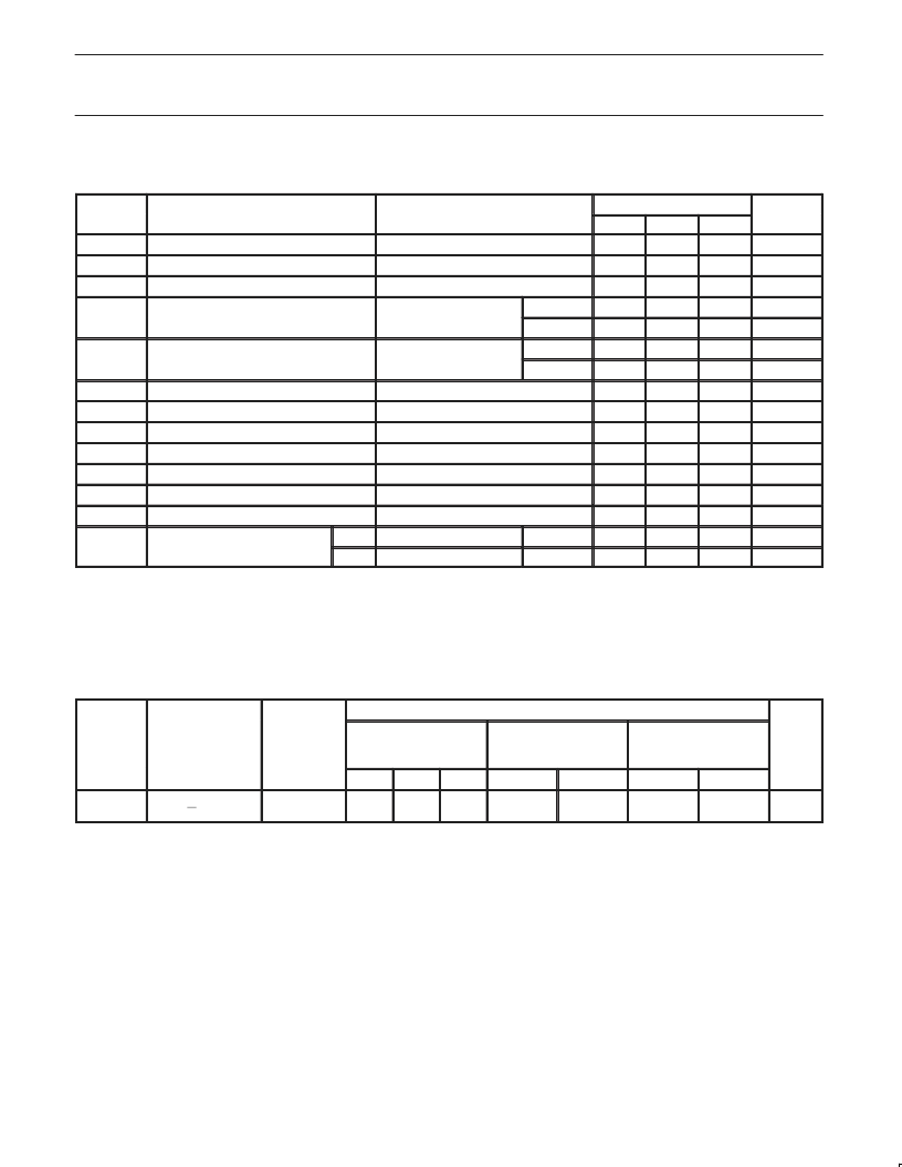
DC ELECTRICAL CHARACTERISTICS
(Over recommended operating free-air temperature range unless otherwise noted.)
SYMBOL
PARAMETER
TEST CONDITIONS
1
LIMITS
TYP
2
UNIT
MIN
MAX
V
T+
V
T–
V
T
V
OH
Positive-going threshold
V
CC
= 5.0V
V
CC
= 5.0V
V
CC
= 5.0V
V
CC
= MIN, V
I
= V
T–MIN
,
I
OH
= MAX
V
CC
= MIN, V
I
= V
T+MAX
,
I
OL
= MAX
V
CC
= MIN, I
I
= I
IK
V
CC
= 5.0V, V
I
= V
T+
V
CC
= 5.0V, V
I
= V
T–
V
CC
= MAX, V
I
= 7.0V
V
CC
= MAX, V
I
= 2.7V
V
CC
= MAX, V
I
= 0.5V
V
CC
= MAX
V
CC
= MAX
V
CC
= MAX
1.4
1.7
2.0
V
Negative-going threshold
0.7
0.9
1.1
V
Hysteresis (V
T+
– V
T–
)
High-level output voltage
0.4
0.8
V
±
10%V
CC
±
5%V
CC
±
10%V
CC
±
5%V
CC
2.5
V
2.7
3.4
V
V
OL
Low-level output voltage
0.30
0.50
V
0.30
0.50
V
V
IK
I
T+
I
T–
I
I
I
IH
I
IL
I
OS
I
CC
Input clamp voltage
-0.73
-1.2
V
Input current at positive-going threshold
0
μ
A
μ
A
μ
A
Input current at negative-going threshold
–175
Input current at maximum input voltage
100
High-level input current
20
μ
A
Low-level input current
Short-circuit output current
3
-0.6
mA
-60
-150
mA
Supply current (total)
I
CCH
I
CCL
V
IN
= GND
V
IN
= 4.5V
13
22
mA
23
32
mA
NOTES:
1
For conditions shown as MIN or MAX, use the appropriate value specified under recommended operating conditions for the applicable type.
2
All typical values are at V
CC
= 5V, T
amb
= 25
°
C.
3
Not more than one output should be shorted at a time. For testing I
OS
, the use of high-speed test apparatus and/or sample-and-hold
techniques are preferable in order to minimize internal heating and more accurately reflect operational values. Otherwise, prolonged shorting
of a high output may raise the chip temperature well above normal and thereby cause invalid readings in other parameter tests. In any
sequence of parameter tests, I
OS
tests should be performed last.
AC ELECTRICAL CHARACTERISTICS
LIMITS
SYMBOL
PARAMETER
TEST
CONDITION
V
CC
= +5.0V
T
amb
= +25
°
C
C
L
= 50pF, R
L
= 500
V
CC
= +5.0V
±
10%
T
amb
= 0
°
C to +70
°
C
C
L
= 50pF, R
L
= 500
V
CC
= +5.0V
±
10%
T
amb
= –40
°
C to +85
°
C
C
L
= 50pF, R
L
= 500
UNIT
MIN
TYP
MAX
MIN
MAX
MIN
MAX
t
PLH
t
PHL
Propagation delay
Dn to Qn
Waveform 1
4.0
3.5
6.5
5.0
8.5
6.5
4.0
3.5
9.5
7.0
3.0
3.5
10.5
9.0
ns
相關PDF資料 |
PDF描述 |
|---|---|
| 74F14 | Hex Inverter Schmitt Trigger |
| 74F14PC | Hex Inverter Schmitt Trigger |
| 74F14SC | Hex Inverter Schmitt Trigger |
| 74F14SJ | Hex Inverter Schmitt Trigger |
| 74F14 | SCHMITT TRIGGERS DUAL 4-INPUT NAND/HEX INVERTERS |
相關代理商/技術參數 |
參數描述 |
|---|---|
| 74F14Z6B_BAC UP WAF | 制造商:Rochester Electronics LLC 功能描述: |
| 74F151 | 制造商:FAIRCHILD 制造商全稱:Fairchild Semiconductor 功能描述:8-Input Multiplexer |
| 74F151A | 制造商:FAIRCHILD 制造商全稱:Fairchild Semiconductor 功能描述:8-Input Multiplexer |
| 74F151A_WHH3026B WAF | 制造商:Fairchild Semiconductor Corporation 功能描述: |
| 74F151ADC | 制造商:FCS 功能描述: |
發(fā)布緊急采購,3分鐘左右您將得到回復。