- 您現(xiàn)在的位置:買賣IC網(wǎng) > PDF目錄369295 > 74ACT161SCX (FAIRCHILD SEMICONDUCTOR CORP) Complete, Dual, 12-Bit Multiplying DAC with 8-Bit Bus Interface PDF資料下載
參數(shù)資料
| 型號: | 74ACT161SCX |
| 廠商: | FAIRCHILD SEMICONDUCTOR CORP |
| 元件分類: | 通用總線功能 |
| 英文描述: | Complete, Dual, 12-Bit Multiplying DAC with 8-Bit Bus Interface |
| 中文描述: | ACT SERIES, SYN POSITIVE EDGE TRIGGERED 4-BIT UP BINARY COUNTER, PDSO16 |
| 封裝: | 0.150 INCH, MS-012, SOIC-16 |
| 文件頁數(shù): | 5/11頁 |
| 文件大?。?/td> | 97K |
| 代理商: | 74ACT161SCX |

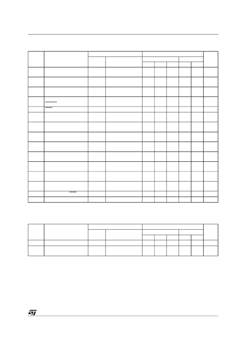
AC ELECTRICAL CHARACTERISTICS
(C
L
= 50 pF, R
L
= 500
, Input t
r
= t
f
=3 ns)
Symbol
Parameter
Test Condition
Value
Unit
V
CC
(V)
5.0
(*)
T
A
= 25
o
C
Min.
Typ.
1.5
-40 to 85
o
C
Min.
Max.
9.5
Max.
10.5
t
PLH
t
PHL
t
PLH
t
PHL
t
PLH
t
PHL
t
PHL
Propagation Delay Time
CKto Q
Propagation Delay Time
CKto CARRYOUT
Propagation Delay Time
TEto CARRYOUT
Propagation Delay Time
CLEAR to CARRYOUT
CLRpulseWidth, LOW
CKpulse Width (LOAD)
HIGHorLOW
CKpulse Width (COUNT)
HIGHorLOW
SetupTime HIGH orLOW
(INPUTto CK)
Hold TimeHIGH or LOW
(INPUTto CK)
SetupTime HIGH orLOW
(LOAD to CK)
Hold TimeHIGH or LOW
(LOAD to CK)
SetupTime HIGH orLOW
(PE orTE to CK)
Hold TimeHIGH or LOW
(PE orTE to CK)
Recovery Time CLR to Q
Maximum Clock Frequency
(*) Voltagerangeis5V
±
0.5V
5.5
ns
5.0
(*)
1.5
7.0
11.0
12.0
ns
5.0
(*)
1.5
5.5
8.5
10.0
ns
5.0
(*)
1.5
6.0
10.0
11.0
ns
t
wL
t
w
5.0
(*)
5.0
(*)
2.5
2.0
3.0
3.0
7.5
3.5
ns
ns
t
w
5.0
(*)
2.0
3.0
3.5
ns
t
s
5.0
(*)
1.5
9.5
11.5
ns
t
h
5.0
(*)
-0.5
0
1.0
ns
t
s
5.0
(*)
2.0
8.5
9.5
ns
t
h
5.0
(*)
-2.0
-0.5
0
ns
t
s
5.0
(*)
1.5
5.5
6.5
ns
t
h
5.0
(*)
-2.0
0
0.5
ns
t
REM
f
MAX
5.0
(*)
5.0
(*)
-0.5
125
0.5
1.0
ns
115
100
MHz
CAPACITIVE CHARACTERISTICS
Symbol
Parameter
Test Conditions
Value
Unit
V
CC
(V)
T
A
= 25
o
C
Min.
Typ.
-40 to 85
o
C
Min.
Max.
Max.
C
IN
C
PD
Input Capacitance
Power Dissipation
Capacitance (note 1)
5.0
5.0
4.5
45
pF
pF
f
IN
= 10 MHz
1)C
PD
isdefined as thevalue oftheIC’sinternal equivalent capacitance whichiscalculated fromtheoperatingcurrent consumption without load.(Referto
TestCircuit).Average opertingcurrent canbeobtained bythefollowingequation. I
CC
(opr)=C
PD
V
CC
f
IN
+I
CC
/n(per circuit)
74ACT161
5/11
發(fā)布緊急采購,3分鐘左右您將得到回復(fù)。