- 您現(xiàn)在的位置:買賣IC網(wǎng) > PDF目錄298491 > 711-17E24-12SF(416) (AMPHENOL CORP) 12 CONTACT(S), FEMALE, CIRCULAR CONNECTOR, CRIMP, RECEPTACLE PDF資料下載
參數(shù)資料
| 型號: | 711-17E24-12SF(416) |
| 廠商: | AMPHENOL CORP |
| 元件分類: | 圓形連接器 |
| 英文描述: | 12 CONTACT(S), FEMALE, CIRCULAR CONNECTOR, CRIMP, RECEPTACLE |
| 文件頁數(shù): | 12/12頁 |
| 文件大小: | 631K |
| 代理商: | 711-17E24-12SF(416) |

9
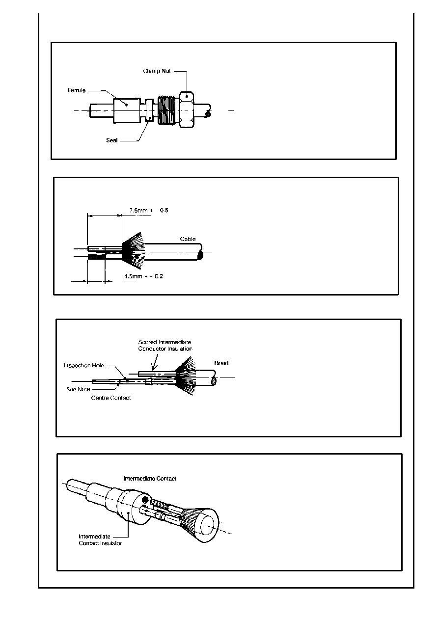
Size #10 Data Bus Contact Assembly Instructions
Slide clamp nut, seal and ferrule over cable.
(Nut & seal only applicable on single way
connector).
Remove outer sheath of cable to 7.5mm comb out all
braids evenly and fold back. Remove cable fillers from
stripped length. Strip the centre contact conductor to
4.5mm. Note: It is recommended that both
intermediate and centre contact conductors are
scored at the correct stripping length. The
intermediate conductor insulation should not be
removed until the centre contact has been crimped.
Crimp centre contact (Pin or Socket) on to the
stripped wire using tool M22520/2-01 and crimp
positioner 294GB-5027-1 (setting No. 4 for 24AWG)
butting rear end of contact to wire insulation. The
conductor end should be visible in the inspection
hole. Note: A second hole is permissible in the
socket contact for manufacturing purposes. It is not
required to be on the same centre line as the
inspection hole.
Strip intermediate contact conductor to 4.5mm.
Insert centre contact into centre hole of intermediate
contact conductor into the outer hole of the
intermediate contact assembly. Push firmly home
until the centre contact is felt to snap into place and
ensure that the insulation of each conductor is fully
inserted into the intermediate contact insulator. The
intermediate conductor should be visible in the
inspection hole in the intermediate contact. There
should be no loose cable strands visible. Crimp the
intermediate contact assembly using the appropriate
cavity of crimp jaw 294GB-5026-1 fitted into
M22520/5-01 tool.
相關(guān)PDF資料 |
PDF描述 |
|---|---|
| 711-17E | FEMALE; MALE, CIRCULAR CONNECTOR, CRIMP, RECEPTACLE |
| 711220 | MALE-FEMALE, RF STRAIGHT ADAPTER |
| 711222 | FEMALE-FEMALE, RF STRAIGHT ADAPTER |
| 711240 | MALE-FEMALE, RF STRAIGHT ADAPTER |
| 711410 | MALE-FEMALE, RF STRAIGHT ADAPTER |
相關(guān)代理商/技術(shù)參數(shù) |
參數(shù)描述 |
|---|---|
| 711-180A115 | 制造商:TE Connectivity 功能描述: |
| 711-180A26 | 制造商:TE Connectivity 功能描述: |
| 711-180B115 | 制造商:TE Connectivity 功能描述: |
| 711182 | 制造商:Phoenix Contact 功能描述:VDFK 4/K GNYE (VE500) |
| 711-182 | 制造商:WAGO Innovative Connections 功能描述: |
發(fā)布緊急采購,3分鐘左右您將得到回復(fù)。