- 您現(xiàn)在的位置:買賣IC網(wǎng) > PDF目錄91653 > 5KP170AT 5000 W, UNIDIRECTIONAL, SILICON, TVS DIODE PDF資料下載
參數(shù)資料
| 型號: | 5KP170AT |
| 元件分類: | TVS二極管 - 瞬態(tài)電壓抑制 |
| 英文描述: | 5000 W, UNIDIRECTIONAL, SILICON, TVS DIODE |
| 封裝: | PLASTIC, CASE P600, 2 PIN |
| 文件頁數(shù): | 3/4頁 |
| 文件大小: | 158K |
| 代理商: | 5KP170AT |
Silicon Avalanche Diodes
300
www .littelfuse .com
5000 Watt Axial Leaded Transient Voltage Suppressor
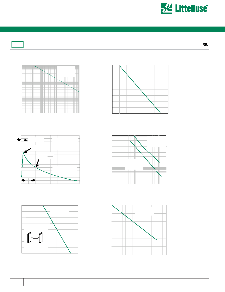
Fig. 1 Peak Pulse Power Rating Curve
Fig. 2 Pulse Derating Curve
Fig. 3 Pulse Waveform
Fig. 4- Typical Junction Capacitance
Fig. 6- Maximum Non-repetitive Forward
Surge Current
I FSM
,Peak
Forward
Surge
Current
(A)
100
150
200
250
300
350
400
100
10
1
Number of Cycles at 60HZ
Fig. 5 Steady State Power
Derating Curve
I PPM
-Peak
Pulse
Current,
%
I
RSM
0
50
100
150
1.0
2.0
3.0
4.0
tr=10sec
Peak Value
IPPM
Half Value IPPM
2
TJ=25C
Pulse Width(td) is defined
as the point where the peak
current decays to 50% of IPPM
10/1000sec. Waveform
as defined by R.E.A
td
t-Time (ms)
TL- Lead Temperature (C)
Steady
State
Power
Dissipation
(W)
0
25
2
50
75
6
4
100
8
125 150 175 200
L=0.375(9.5mm)
Lead Lengths
0.8x0.8x.040''
(20x20mm)
Copper Heat Sinks
60HZ
Resistive or
Inductive Load
TA- Ambient Temperature (C)
Peak
Pulse
Power
(KW)
0
25
50
75
100
125 150 175 200
C
J-Junction
Capacitance
(pF)
1
1000
100
10000
100000
10
100 200
Vbr, Breakdown Voltage
TJ=25C
f=1MH2
Vsig=50mVp-p
Measured at
Stand-off
Voltage
8.3ms Single
Half Sine-Wave
P
PPM
-Peak
Pulse
Power
(kW)
0.1s
1.0s
10s
100s
1.0ms
10ms
0.1
1
10
100
td- Pulse Width (sec.)
Non-repetitive pulse
waveform shown in
Fig.3 TA=25C
Ratings and Characteristic Curves TA=25C unless otherwise noted
5KP Series
RoHS
發(fā)布緊急采購,3分鐘左右您將得到回復(fù)。