- 您現(xiàn)在的位置:買賣IC網(wǎng) > PDF目錄67325 > 5962-9065401MEA (TEXAS INSTRUMENTS INC) 8-CHANNEL, SGL ENDED MULTIPLEXER, CDIP16 PDF資料下載
參數(shù)資料
| 型號: | 5962-9065401MEA |
| 廠商: | TEXAS INSTRUMENTS INC |
| 元件分類: | 多路復(fù)用及模擬開關(guān) |
| 英文描述: | 8-CHANNEL, SGL ENDED MULTIPLEXER, CDIP16 |
| 封裝: | CERAMIC, DIP-16 |
| 文件頁數(shù): | 26/29頁 |
| 文件大?。?/td> | 736K |
| 代理商: | 5962-9065401MEA |
第1頁第2頁第3頁第4頁第5頁第6頁第7頁第8頁第9頁第10頁第11頁第12頁第13頁第14頁第15頁第16頁第17頁第18頁第19頁第20頁第21頁第22頁第23頁第24頁第25頁當(dāng)前第26頁第27頁第28頁第29頁
6
Absolute Maximum Ratings (Note 2)
Thermal Information
DC Supply Voltage, VCC - VEE . . . . . . . . . . . . . . . . . -0.5V to 10.5V
DC Supply Voltage, VCC . . . . . . . . . . . . . . . . . . . . . . . . . . . . -0.5V to +7V
DC Supply Voltage, VEE . . . . . . . . . . . . . . . . . . . . . . . . . . . . +0.5V to -7V
DC Input Diode Current, IIK
For VI < -0.5V or VI > VCC + 0.5V . . . . . . . . . . . . . . . . . . . . . .±20mA
DC Switch Diode Current, IOK
For VI < VEE -0.5V or VI > VCC + 0.5V . . . . . . . . . . . . . . . . .±20mA
DC Switch Current, (Note 2)
For VI > VEE -0.5V or VI < VCC + 0.5V . . . . . . . . . . . . . . . . .±25mA
DC VCC or Ground Current, ICC . . . . . . . . . . . . . . . . . . . . . . . . .±50mA
DC VEE Current, IEE . . . . . . . . . . . . . . . . . . . . . . . . . . . . . . . -20mA
Package Thermal Impedance,
θJA (see Note 1):
E (PDIP) Package . . . . . . . . . . . . . . . . . . . . . . . . . . . . . . . 67oC/W
M (SOIC) Package. . . . . . . . . . . . . . . . . . . . . . . . . . . . . . . 73oC/W
NS (SOP) Package . . . . . . . . . . . . . . . . . . . . . . . . . . . . . . 64oC/W
PW (TSSOP) Package . . . . . . . . . . . . . . . . . . . . . . . . . . 108oC/W
Maximum Junction Temperature . . . . . . . . . . . . . . . . . . . . . . . 150oC
Maximum Storage Temperature Range . . . . . . . . . .-65oC to 150oC
Maximum Lead Temperature (Soldering 10s) . . . . . . . . . . . . . 300oC
NOTE:
1. The package thermal impedance is calculated in accordance with JESD 51-7.
Recommended Operating Conditions
For maximum reliability, nominal operating conditions should be selected so that
operation is always within the following ranges
PARAMETER
MIN
MAX
UNITS
Supply Voltage Range (For TA = Full Package Temperature Range), VCC (Note 2)
CD54/74HC Types
26
V
CD54/74HCT Types
4.5
5.5
V
Supply Voltage Range (For TA = Full Package Temperature Range), VCC - VEE
CD54/74HC Types, CD54/74HCT Types (See Figure 1)
2
10
V
Supply Voltage Range (For TA = Full Package Temperature Range), VEE (Note 3)
CD54/74HC Types, CD54/74HCT Types (See Figure 2)
0
-6
V
DC Input Control Voltage, VI
GND
VCC
V
Analog Switch I/O Voltage, VIS
VEE
VCC
V
Operating Temperature, TA
-55
125
oC
Input Rise and Fall Times, tr, tf
2V
0
1000
ns
4.5V
0
500
ns
6V
0
400
ns
CAUTION: Stresses above those listed in “Absolute Maximum Ratings” may cause permanent damage to the device. This is a stress only rating and operation
of the device at these or any other conditions above those indicated in the operational sections of this specication is not implied.
NOTES:
2. All voltages referenced to GND unless otherwise specified.
.
3. In certain applications, the external load resistor current may include both VCC and signal line components. To avoid drawing VCC current
when switch current flows into the transmission gate inputs, the voltage drop across the bidirectional switch must not exceed 0.6V (cal-
culated from rON values shown in Electrical Specifications table). No VCC current will flow through RL if the switch current flows into
terminal 3 on the HC/HCT4051; terminals 3 and 13 on the HC/HCT4052; terminals 4, 14 and 15 on the HC/HCT4053.
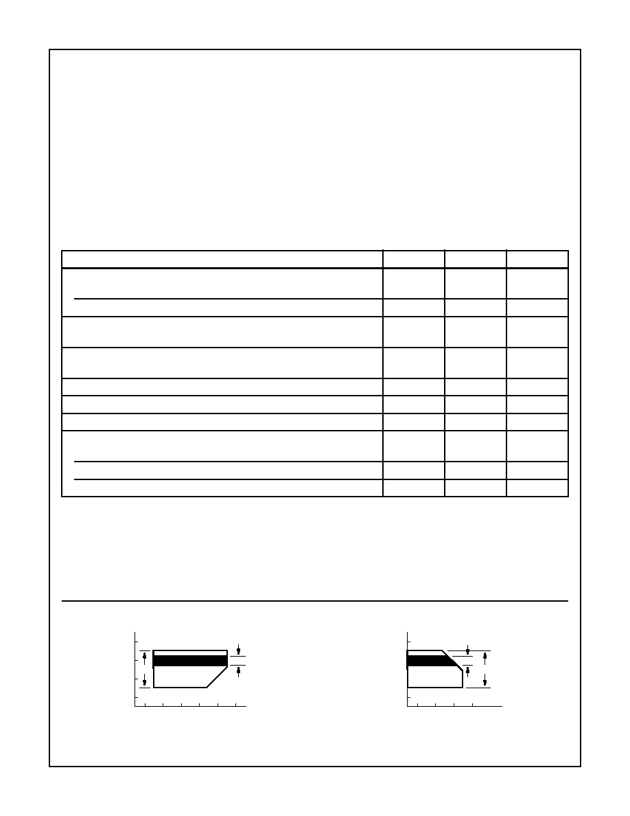
Recommended Operating Area as a Function of Supply Voltages
FIGURE 1.
FIGURE 2.
HCT
V
CC
-
GND
(V)
VCC - VEE (V)
8
6
4
2
0
2468
10
12
HC
HCT
V
CC
-
GND
(V)
VEE - GND (V)
8
6
4
2
0
0-2
-4
-6
-8
HC
’HC4051, ’HCT4051, ’HC4052, CD74HCT4052, ’HC4053, CD74HCT4053
相關(guān)PDF資料 |
PDF描述 |
|---|---|
| 5962-8776202VX | 1-CH 8-BIT SUCCESSIVE APPROXIMATION ADC, PARALLEL ACCESS, CDIP18 |
| 5962-87786-01VA | 1-CH 6-BIT FLASH METHOD ADC, PARALLEL ACCESS, CDIP18 |
| 5962-87786-01VX | 1-CH 6-BIT FLASH METHOD ADC, PARALLEL ACCESS, CDIP18 |
| TDC1046B8C | 1-CH 6-BIT FLASH METHOD ADC, PARALLEL ACCESS, CDIP18 |
| TDC1046B8V | 1-CH 6-BIT FLASH METHOD ADC, PARALLEL ACCESS, CDIP18 |
相關(guān)代理商/技術(shù)參數(shù) |
參數(shù)描述 |
|---|---|
| 59629065801KA | 制造商:WSI 功能描述:New |
| 5962-9065801KA | 制造商:STMicroelectronics 功能描述:WS57C43C-70FMB |
| 5962-90658023A | 制造商:QP Semiconductor 功能描述:EPROM UV 32K-Bit 4K x 8 55ns 28-Pin LLCC |
| 5962-90658023C | 制造商:QP Semiconductor 功能描述:EPROM UV 32K-Bit 4K x 8 55ns 28-Pin LLCC |
| 5962-9065802JA | 制造商:WSI 功能描述: |
發(fā)布緊急采購,3分鐘左右您將得到回復(fù)。