- 您現(xiàn)在的位置:買賣IC網(wǎng) > PDF目錄67336 > 5962-0621301HXC (CRANE ELECTRONICS INC) 1-OUTPUT 40 W DC-DC REG PWR SUPPLY MODULE PDF資料下載
參數(shù)資料
| 型號: | 5962-0621301HXC |
| 廠商: | CRANE ELECTRONICS INC |
| 元件分類: | 電源模塊 |
| 英文描述: | 1-OUTPUT 40 W DC-DC REG PWR SUPPLY MODULE |
| 封裝: | HERMETIC SEALED PACKAGE-12 |
| 文件頁數(shù): | 12/13頁 |
| 文件大?。?/td> | 638K |
| 代理商: | 5962-0621301HXC |

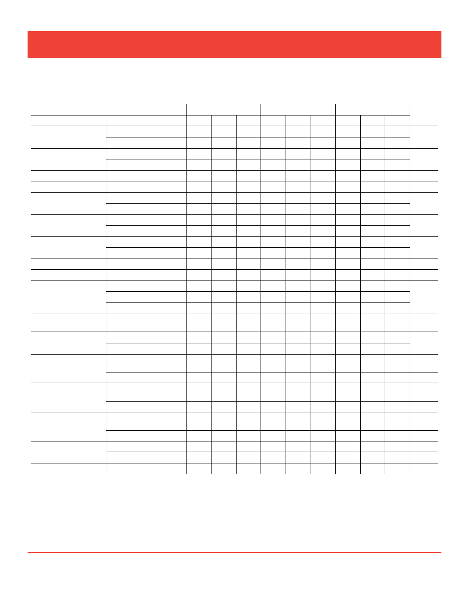
Electrical Characteristics: -55°C to +125°C TC, 28 VDC VIN, 100% load, free run, unless otherwise specified.
notes:
1. Guaranteed by design, not tested.
2. Parallel load share function is not characterized for dual output models.
3. Up to 70% of the total output power is available from either output providing the
opposite output is simultaneously carrying 30% of the total power.
4. Effect on negative Vout from 50%/50% loads to 70%/30% or
30%/70% loads.
5. Effect on negative Vout from 50%/50% loads to 50% then 10% load on negative
Vout.
6. Unit will shut down above approximately 45V but will be undamaged and will
restart when voltage drops into normal range.
7. Transition time 100 s ±20%.
8. Recovery time is measured from application of the transient to point at which Vout
is within 1% of final value.
9. Tested on release from inhibit.
10. Shall not compromise DC performance.
DUAL OUTPUT MODELS 2
MFL2805D
MFL2812D
MFL2815D
units
Parameter
cOnDitiOns
MIN
TYP
MAX
MIN
TYP
MAX
MIN
TYP
MAX
OutPut VOltage
+ VOut 4.85
5.00
5.15
11.64 12.00 12.36 14.55 15.00 15.45
VDc
- VOut 4.82
5.00
5.18
11.58 12.00 12.42 14.47 15.00 15.53
OutPut current 3
each OutPut
0
—
7
0
—
3.5
0
—
3.03
a
Vin = 16 tO 40 VDc
tOtal OutPut
0
—
10
0
—
5
0
—
4.34
OutPut POWer 3
Vin = 16 tO 40 VDc
0
—
50
0
—
60
0
—
65
W
OutPut riPPle
10 khz - 2 mhz ± VOut
—
50
100
—
50
120
—
50
150
mV p-p
line regulatiOn
+ VOut
—
0
50
—
0
50
—
0
50
mV
Vin = 16 tO 40 VDc
- VOut
—
25
100
—
25
100
—
25
100
lOaD regulatiOn
+ VOut
—
0
50
—
10
50
—
10
50
mV
nO lOaD tO Full
- VOut
—
25
100
—
25
120
—
50
150
crOss regulatiOn
see nOte 4
—
5
8
—
2
4
—
2
4
%
tc = 25°c
see nOte 5
—
3
7
—
2
4
—
2
4
inPut VOltage
cOntinuOus
16
28
40
16
28
40
16
28
40
VDc
nO lOaD tO Full
TRANSIENT 50 msec.1, 6
0
—
50
0
—
50
0
—
50
V
inPut current
nO lOaD
—
50
120
–
50
100
—
50
100
inhibiteD–inh1
—
9
14
—
9
14
—
9
14
mA
inhibiteD–inh2
—
35
70
—
35
70
—
35
70
inPut riPPle
current
10 khz - 10 mhz
—
15
50
—
15
50
—
15
50
mA p-p
eFFiciency
tc = 25°c
77
80
—
83
86
—
84
87
—
%
balanceD lOaD
tc = -55°c tO +125°c
75
—
81
—
82
—
lOaD Fault
POWer DissiPatiOn
shOrt circuit
—
12.5
18
—
10
16
—
10
16
W
recOVery 1
—
1.5
4
—
1.5
4
—
1.5
4.0
ms
steP lOaD
resPOnse 7
50% - 100% - 50%
transient
—
250
350
—
450
600
—
500
600
mV pk
± VOut
recOVery 1, 8
—
1.5
3.0
—
1.5
3.0
—
1.5
3.0
ms
steP line
resPOnse 1, 7
16 - 40 -16 VDc
transient
—
250
300
—
250
400
—
250
500
mV pk
± VOut
recOVery 8
—
200
300
—
200
300
—
200
300
s
start-uP 9
Delay
—
3.5
6
—
3.5
6
—
3.5
6
ms
OVershOOt 1
—
0
25
—
0
50
—
0
50
mV pk
caPacitiVe lOaD 1, 10
tc = 25°c
—
500
—
500
—
500
F
Crane Aerospace & Electronics Power Solutions
MFL single and dual dc/dc converters
28 VoLt input – 65 Watt
www.craneae.com/interpoint
Page 8 of 13
MFL Rev H - 2011.07.07
相關(guān)PDF資料 |
PDF描述 |
|---|---|
| 5962-9319301HXC | 2-OUTPUT 60 W DC-DC REG PWR SUPPLY MODULE |
| 5962-9320401MEA | SERIAL INPUT LOADING, 12-BIT DAC, CDIP16 |
| 5962-9322201MEA | VOLTAGE-FREQUENCY CONVERTER, 4 MHz, CDIP16 |
| 5962-9326101MEA | 1.5 A POWER FACTOR CONTROLLER, 118 kHz SWITCHING FREQ-MAX, CDIP16 |
| 5962-9326101M2A | 1.5 A POWER FACTOR CONTROLLER, 118 kHz SWITCHING FREQ-MAX, QCC20 |
相關(guān)代理商/技術(shù)參數(shù) |
參數(shù)描述 |
|---|---|
| 5962-0622901QXC | 制造商:ATMEL 制造商全稱:ATMEL Corporation 功能描述:Rad Hard 16 MegaBit 3.3V 5V Tolerant SRAM Multi- Chip Module |
| 5962-0622901VXC | 制造商:ATMEL 制造商全稱:ATMEL Corporation 功能描述:Rad Hard 16 MegaBit 3.3V 5V Tolerant SRAM Multi-Chip Module |
| 5962-0622902QXC | 制造商:ATMEL 制造商全稱:ATMEL Corporation 功能描述:Rad Hard 16 MegaBit 3.3V SRAM MultiChip Module |
| 5962-0622902VXC | 制造商:ATMEL 制造商全稱:ATMEL Corporation 功能描述:Rad Hard 16 MegaBit 3.3V SRAM MultiChip Module |
| 5962-0622903QYC | 制造商:ATMEL 制造商全稱:ATMEL Corporation 功能描述:Rad Hard 16 MegaBit 3.3V 5V Tolerant SRAM Multi- Chip Module |
發(fā)布緊急采購,3分鐘左右您將得到回復(fù)。