- 您現(xiàn)在的位置:買賣IC網(wǎng) > PDF目錄67320 > 5962-005300HXX (ANALOG DEVICES INC) DUAL 1-CH 12-BIT PROPRIETARY METHOD ADC, PARALLEL ACCESS, CQFP68 PDF資料下載
參數(shù)資料
| 型號: | 5962-005300HXX |
| 廠商: | ANALOG DEVICES INC |
| 元件分類: | ADC |
| 英文描述: | DUAL 1-CH 12-BIT PROPRIETARY METHOD ADC, PARALLEL ACCESS, CQFP68 |
| 封裝: | CERAMIC, LCC-68 |
| 文件頁數(shù): | 4/20頁 |
| 文件大小: | 3346K |
| 代理商: | 5962-005300HXX |
This information applies to a product which is in development. Specifications are subject to change without notice. Contact factory for most
recent information. Analog Devices Sensitive Material - not to be reproduced or distributed without permission.
Rev. Pr E
12
LAYOUT INFORMATION
The schematic of the evaluation board (Figure 9.) represents a typical
implementation of the AD13280. The pinout of the AD13280 is very
straightforward and facilitates ease of use and the implementation of
high frequency/high resolution design practices. It is recommended that
high quality ceramic chip capacitors be used to decouple each supply
pin to ground directly at the device. All capacitors can be standard high
quality ceramic chip capacitors.
Care should be taken when placing the digital output runs. Because the
digital outputs have such a high-slew rate, the capacitive loading on the
digital outputs should be minimized. Circuit traces for the digital
outputs should be kept short and connect directly to the receiving gate.
Internal circuitry buffers the outputs of the ADC through a resistor
network to eliminate the need to externally isolate the device from the
receiving gate.
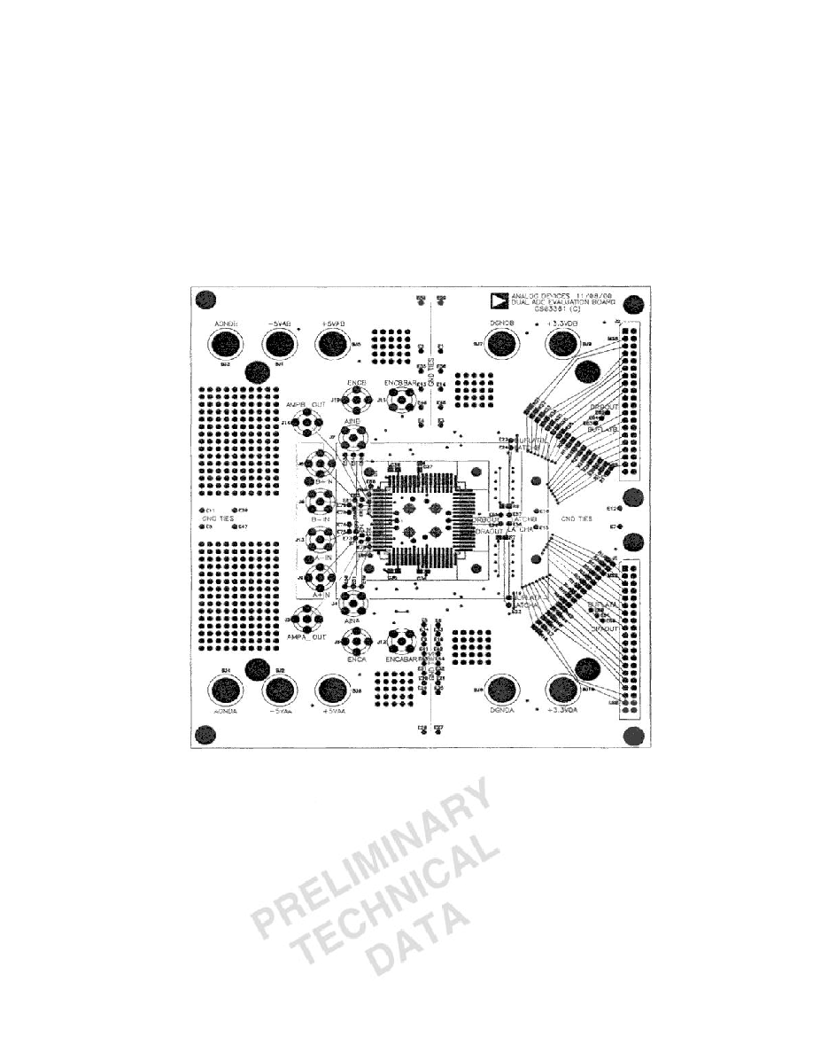
EVALUATION BOARD
The AD13280 evaluation board (Figure 10.) is designed to provide
optimal performance for evaluation of the AD13280 analog-to-digital
converter. The board encompasses everything needed to insure the
highest level of performance for evaluating the AD13280. The board
requires an analog input signal, encode clock and power supply inputs.
The clock is buffered on-board to provide clocks for the latches. The
digital outputs and out clocks are available at the standard 40-pin
connectors J1 and J2.
Power to the analog supply pins is connected via banana jacks. The
analog supply powers the associated components and the analog section
of the AD13280. The digital outputs of the AD13280 are powered via
banana jacks with 3.3V. Contact the factory if additional layout or
applications assistance is required.
AD13280
Figure 9. Evaluation Board Mechanical Layout
相關(guān)PDF資料 |
PDF描述 |
|---|---|
| 5962-0150601HXX | DUAL 1-CH 14-BIT PROPRIETARY METHOD ADC, PARALLEL ACCESS, CQFP68 |
| 5962-0251002HXC | 1-OUTPUT 8 W DC-DC REG PWR SUPPLY MODULE |
| 5962-9213902HZC | 1-OUTPUT 12 W DC-DC REG PWR SUPPLY MODULE |
| 5962-9555902HXC | 2-OUTPUT 12 W DC-DC REG PWR SUPPLY MODULE |
| 5962-9214402HXC | 2-OUTPUT 15 W DC-DC REG PWR SUPPLY MODULE |
相關(guān)代理商/技術(shù)參數(shù) |
參數(shù)描述 |
|---|---|
| 5962005304899 | 制造商: 功能描述: 制造商:undefined 功能描述: |
| 5962005308115 | 制造商: 功能描述: 制造商:undefined 功能描述: |
| 5962005345643 | 制造商: 功能描述: 制造商:undefined 功能描述: |
| 5962-0053901QYA | 制造商:TI 制造商全稱:Texas Instruments 功能描述:DIGITAL SIGNAL PROCESSOR |
| 5962-0053901QYC | 制造商:TI 制造商全稱:Texas Instruments 功能描述:DIGITAL SIGNAL PROCESSOR |
發(fā)布緊急采購,3分鐘左右您將得到回復(fù)。