- 您現(xiàn)在的位置:買賣IC網(wǎng) > PDF目錄371605 > 522962A Dual/Triple Ultra-Low-Voltage SOT23 µP Supervisory Circuits PDF資料下載
參數(shù)資料
| 型號: | 522962A |
| 英文描述: | Dual/Triple Ultra-Low-Voltage SOT23 µP Supervisory Circuits |
| 中文描述: | IC-SM-DC/DC轉(zhuǎn)爐 |
| 文件頁數(shù): | 11/12頁 |
| 文件大?。?/td> | 287K |
| 代理商: | 522962A |

11
LT1175
APPLICATIO
S I
FOR
ATIO
U
To estimate regulator output ripple under different condi-
tions, the following general comments should be helpful:
1. Output ripple at high frequency is only weakly affected
by load current or output capacitor size for medium to
heavy loads. At very light loads (<10mA), higher fre-
quency ripple may be reduced by using larger output
capacitors.
2. A feedforward capacitor across the resistor divider
used with the adjustable part is effective in reducing
ripple only for output voltages greater than 5V and only
for frequencies less than 100kHz.
3. Input-to-output voltage differential has little effect on
ripple rejection until the regulator actually enters a
dropout condition of 0.2V to 0.6V.
If ripple rejection needs to be improved, an input filter can
be added. This filter can be a simple RC filter using a 1
to 10
resistor. A 3.3
resistor for instance, combined
with a 0.3
ESR solid tantalum capacitor, will give an
additional 20dB ripple rejection. The size of the resistor
will be dictated by maximum load current. If the maximum
voltage drop allowable across the resistor is “V
R
,” and
maximum load current is I
LOAD
, R = V
R
/I
LOAD
. At light
loads, larger resistors and smaller capacitors can be used
W
U
U
Dimensions in inches (millimeters) unless otherwise noted.
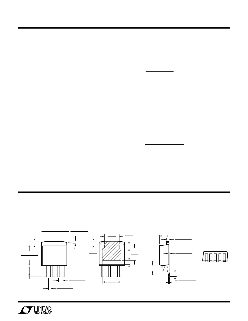
PACKAGE DESCRIPTIO
N
U
to save space. At heavier loads an inductor may have to be
used in place of the resistor. The value of the inductor can
be calculated from:
L
ESR
10
f
FIL
rr
=
( )
(
)
2
20
π
/
ESR = Effective series resistance of filter capacitor. This
assumes that the capacitive reactance is small
compared to ESR, a reasonable assumption for
solid tantalum capacitors above 2.2
μ
F and 50kHz.
f
= Ripple frequency
rr
= Ripple rejection ratio of filter in dB
Example: ESR = 1.2
, f = 100kHz, rr = –25dB.
L
H
FIL
=
=
1 2
10
6 3 10
.
34
5
25 20
/
.
μ
Solid tantalum capacitors are suggested for the filter to
keep filter Q fairly low. This prevents unwanted ringing at
the resonant frequency of the filter and oscillation prob-
lems with the filter/regulator combination.
Information furnished by Linear Technology Corporation is believed to be accurate and reliable.
However, no responsibility is assumed for its use. Linear Technology Corporation makes no represen-
tation that the interconnection of its circuits as described herein will not infringe on existing patent rights.
Q(DD5) 0695
0.013 – 0.023
(0.330 – 0.584)
0.095 – 0.115
(2.413 – 2.921)
0.004–0.004
0.102–0.102
(
)
0.050
±
0.012
(1.270
±
0.305)
0.059
(1.499)
TYP
0.045 – 0.055
(1.143 – 1.397)
0.165 – 0.180
(4.191 – 4.572)
0.028 – 0.038
(0.711 – 0.965)
0.143–0.020
3.632–0.508
(
)
0.057 – 0.077
(1.447 – 1.955)
0.330 – 0.370
(8.382 – 9.398)
0.060
(1.524)
TYP
0.390 – 0.415
(9.906 – 10.541)
15
°
TYP
0.300
(7.620)
0.075
(1.905)
0.183
(4.648)
0.060
(1.524)
0.060
(1.524)
0.256
(6.502)
BOTTOM VIEW OF DD PAK
HATCHED AREA IS SOLDER PLATED
COPPER HEAK SINK
Q Package
5-Lead Plastic DD Pak
(LTC DWG # 05-08-1461)
相關(guān)PDF資料 |
PDF描述 |
|---|---|
| 522963X | IC |
| 522964H | Dual/Triple Ultra-Low-Voltage SOT23 µP Supervisory Circuits |
| 522965F | IC-SWITCHING REGULATOR |
| 522966D | Dual/Triple Ultra-Low-Voltage SOT23 µP Supervisory Circuits |
| 522967B | IC SMD |
相關(guān)代理商/技術(shù)參數(shù) |
參數(shù)描述 |
|---|---|
| 522963X | 制造商:未知廠家 制造商全稱:未知廠家 功能描述:IC |
| 522964H | 制造商:未知廠家 制造商全稱:未知廠家 功能描述:IC-SM-DC/DC CONVERTER |
| 522965F | 制造商:未知廠家 制造商全稱:未知廠家 功能描述:IC-SWITCHING REGULATOR |
| 522966D | 制造商:未知廠家 制造商全稱:未知廠家 功能描述:IC |
| 522967B | 制造商:未知廠家 制造商全稱:未知廠家 功能描述:IC SMD |
發(fā)布緊急采購,3分鐘左右您將得到回復(fù)。