- 您現(xiàn)在的位置:買賣IC網(wǎng) > PDF目錄293828 > 44MGS45-12-1-08S (GRAYHILL INC) ROTARY SWITCH-8POSITIONS, SP8T, LATCHED, 30VDC, PANEL MOUNT-THREADED PDF資料下載
參數(shù)資料
| 型號(hào): | 44MGS45-12-1-08S |
| 廠商: | GRAYHILL INC |
| 元件分類: | 開關(guān) |
| 英文描述: | ROTARY SWITCH-8POSITIONS, SP8T, LATCHED, 30VDC, PANEL MOUNT-THREADED |
| 封裝: | ROHS COMPLIANT |
| 文件頁數(shù): | 11/14頁 |
| 文件大?。?/td> | 293K |
| 代理商: | 44MGS45-12-1-08S |

Grayhill, Inc. 561 Hillgrove Avenue LaGrange, Illinois
60525-5997 USA Phone: 708-354-1040 Fax: 708-354-2820 www.grayhill.com
Rotary
Switches
Multi-Deck Rotary Switches
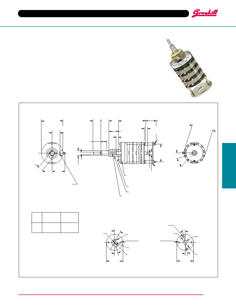
SERIES 54
1" Diameter, 1 Amp, Add-A-Pot
J-56
FEATURES
Military Qualified MIL-3786/04
Central Shaft Designed to Operate
MIL Potentiometer
Mounting Plate Options Provide
Choice of Potentiometer
Fixed Distance from Switch to
Mounting Plate
Military Qualified Style
Note: Common locations for a single pole per
deck switch. For common location on
multiple switches, see circuit diagram.
Number
Approximate
of
Dimension
Weight
Decks
A
Grams
1
1.024 (26,01)
60
2
1.370 (34,80)
67
3
1.716 (43,59)
74
DIMENSIONS In inches (and millimeters)
Potentiometer Mounting
The two mounting plates shown below are supplied with
each switch.
See page J-52 circuit diagrams, 1 pole/deck, 12 positions.
Mounting Plate A
Mounting Plate B
Series 54M Add-A-Pot Switch is a concentric
shaft unit with provision for potentiometer
mounting. Outer shaft operates switch decks.
Inner shaft terminates in tapered tongue,
which allows any desired potentiometer to be
mounted. The Series 54M Add-A-Pot is
qualified to MIL-S-3786/4-3. Patent No.
3,297,830.
Grayhill part number and date code marked on detent
cover label. Customer part number marked on
request. Military part number marked when required.
DIM. A + .046 –.020
(+ 0,05 –0,51)
.642
± .015
(16,31
± 0,38)
NON-TURN TAB
.125 ± .003 (3,18 ± 0,08) WIDE BY
.031 ± .003 (0,79 ± 0,08) THICK
.219 ± .005
(5,56 ± 0,13)
C
L OF NON-TURN
TAB
.375
± .015
(9,53
± 0,38)
1.162 ± .010
(29,51 ± 0,25)
DIA.
.125 + .001 –.002
(3,18 + 0,03 –0,05) DIA.
.250 + .001 –.002
(6,35 + 0,03 –0,05) DIA.
.250 ± .020
(6,35 ± 0,51)
.121 ± .015
(3,07 ± 0,38)
.375
± .020
(9,53
± 0,51)
.375
± .020
(9,53
± 0,51)
.250 ± .020
(6,35 ± 0,51)
.140 ± .062
(3,56 ± 1,57)
1.000
± .010
(25,4
± 0,25)
3/8-32 NEF-2A THREAD
INTEGRAL ASSEMBLY NUT,
DO NOT REMOVE
BUSHING KEYWAY .066 ± .002 (1,68 ± 0,05)
WIDE BY .036 ± .003 (0,91 ± 0,08) DEEP FROM
A .375 (9,53) DIA.
GRAYHILL OR CUSTOMER PART NUMBER
MARKED ON SWITCH COVER UPON REQUEST.
MILITARY NUMBER MARKED ON ALL
QUALIFIED SWITCHES
.575
(14,61)
REF.
#1
THREAD
SEE
POTENTIOMETER
MOUNTING
1.170 ± .015
(29,72 ± 0,38)
OVER TERMINALS
12
9
8
7
6
4
3
2
1
5
11
10
30°
15°
.018 ± .005 (0,46 ± 0,13)
.052 ± .005 (1,32 ± 0,13)
1.265
(32,13)
DIA.
27.5
± 2
.098 ± .003
(2,49 ± 0,08) DIA. (3)
THROUGH BOLT
HOLE (2 EA.)
15
± 2
.245 ± .003
(6,22 ± 0,08) R.
.375 ± .003
(9,53 ± 0,08) R.
.261 ± .003
(6,63 ± 0,08) DIA. (1)
1.265
(32,13)
DIA.
15 ± 2
9
± 2
.437 ± .003
(11,10 ± 0,08) R.
.531 ± .003
(13,49 ± 0,08) R.
.380 ± .003
(9,65 ± 0,08)
DIA. (1)
.130 ± .003
(3,30 ± 0,08)
DIA. (2)
See page J-63 for specifications, accessories
and ordering information.
相關(guān)PDF資料 |
PDF描述 |
|---|---|
| 44MG45-01-1-08S | ROTARY SWITCH-8POSITIONS, SP8T, LATCHED, 0.025A, 28VDC, PANEL MOUNT-THREADED |
| 44US30-01-1-12S | ROTARY SWITCH-12POSITIONS, SP12T, LATCHED, 1A, 28VDC, PANEL MOUNT-THREADED |
| 44HBG90-12-1-04N | ROTARY SWITCH-4POSITIONS, SP4T, LATCHED, 0.025A, 28VDC, PANEL MOUNT-THREADED |
| 450-0028-01-06-00 | BRASS, TIN FINISH, PCB TERMINAL |
| 450-0028-01-03-00 | BRASS, GOLD FINISH, PCB TERMINAL |
相關(guān)代理商/技術(shù)參數(shù) |
參數(shù)描述 |
|---|---|
| 44MGS60-01-1-06N-C | 制造商:Grayhill 功能描述:SWIT ROTARY 6 SHAFT SLDR LUG 115VAC 30VDC - Bulk |
| 44MGS60-01-2-02N | 制造商:Grayhill 功能描述:ROTARY SWITCH, MILITARY 85&DEG, C, LOW LEVEL RATING, SHAFT/PA - Bulk 制造商:Grayhill 功能描述:44MGS60-01-2-02N |
| 44MGS60-01A06N | 制造商:Grayhill 功能描述:Switch Rotary SP6T 6 Flatted Shaft Solder Lug 5A 115VAC 28VDC |
| 44MGS60-01C02N | 功能描述:SWITCH ROTARY 85 DEG;C, LOW LEVE 制造商:grayhill inc. 系列:* 零件狀態(tài):在售 標(biāo)準(zhǔn)包裝:1 |
| 44MGS60-02-1-04N | 制造商:Grayhill 功能描述:ROTARY SWITCH, MILITARY 85°C, LOW LEVEL RATING, SHAFT/PA - Bulk |
發(fā)布緊急采購,3分鐘左右您將得到回復(fù)。