- 您現(xiàn)在的位置:買賣IC網(wǎng) > PDF目錄368897 > 25266 1.8Msps, Single-Supply, Low-Power, True-Differential, 10-Bit ADCs PDF資料下載
參數(shù)資料
| 型號: | 25266 |
| 英文描述: | 1.8Msps, Single-Supply, Low-Power, True-Differential, 10-Bit ADCs |
| 中文描述: | 從Am29DL32xD家庭遷移到Am29DL32xG家庭 |
| 文件頁數(shù): | 2/3頁 |
| 文件大小: | 54K |
| 代理商: | 25266 |
.
Publication#
25266
Issue Date:
August 1, 2001
Rev:
A
Amendment/
0
Migration From Am29DL32xD Family To
Am29DL32xG Family
Application Note
AMD introduced the Secured Silicon (SecSi) Sector
to enable customers to increase system security and
lower system costs. The addition of a SecSi Sector pro-
vided a secure means to provide an Electronic Serial
Number (ESN). Customers can save in system costs
by using the SecSi Sector to replace discrete ID chips
to provide an ESN.
The implementation of the SecSi Sector in the
Am29DL322D, Am29DL323D and Am29DL324D de-
vices using Process Revision D technology is
comprised of 64 Kbytes capable of multiple program-
and-erase cycles. The implementation using Process
Revision G technology introduces three fundamental
changes to the previous implementation:
I
The size of the SecSi Sector is now 256 Bytes.
I
The mapping of the SecSi Sector has been
changed to match the new size and is now located
at the lowest or highest addresses in the device for
bottom or top boot devices respectively.
I
The SecSi Sector can not be erased after being pro-
grammed, that is, it is One Time Programmable
(OTP).
These changes are to provide a less complex imple-
mentation of the SecSi Sector. This Application Note
discusses these implementation changes and their po-
tential effects to customer system design.
Implementation of SecSi Sector in
Process Revision D
The Am29DL322D, Am29DL323D and Am29DL324D
devices offer the SecSi Sector for top boot and bottom
boot sector architectures. The size of the SecSi Sector
is 64 Kbytes. The system accesses the SecSi Sector
through a command sequence.
After the system has written the “Enter SecSi Sector”
command sequence, it may read the SecSi Sector by
using the addresses normally occupied by the boot
sectors. This mode of operation continues until the sys-
tem issues the “Exit SecSi Sector” command
sequence, or until power is removed from the device.
On power-up, or following a hardware reset, the device
reverts to normal read mode.
Thus, for a Bottom Boot device the SecSi Sector over-
lays (replaces) sectors SA0 to SA7 at byte addresses
000000h–00FFFFh. For a Top Boot device the SecSi
Sector overlays sectors SA63 to SA70 at byte ad-
dresses 3F0000h–3FFFFFh. In addition, devices that
have a factory programmed ESN, a Bottom Boot de-
vice will have the 16-byte ESN at byte addresses
00E000h–00E00Fh. A Top Boot device will have the
ESN at byte addresses 3FE000h–3FE00Fh (see Fig-
ure 1).
The SecSi Sector can be read, programmed or erased
just like any other sector, providing additional storage
for code or data if needed.
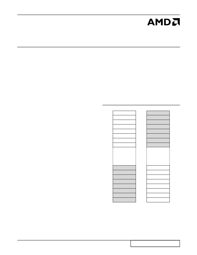
Figure 1. Process Revision D Mapping SecSi
Sector to Bottom (Left) and Top (Right)
Boot Devices
SA07
SA06
SA05
SA04
SA02
SA01
SA00
SA70
SA69
SA68
SA67
SA66
SA65
SA64
SA63
相關(guān)PDF資料 |
PDF描述 |
|---|---|
| 25267B | Interfacing Motorola's MPC56x Microcontroller to AMD's Am29BDD160G Flash Memory |
| 252QS24E | GaAs MMIC SP6T NON-REFLECTIVE SWITCH, DC - 3.0 GHz |
| 2531A | Analog IC |
| 253QS24E | GaAs MMIC SP8T NON-REFLECTIVE SWITCH, DC - 2.5 GHz |
| 254001 | Fuse Blocks and Clips - For NANO2 Surface Mount Fuses |
相關(guān)代理商/技術(shù)參數(shù) |
參數(shù)描述 |
|---|---|
| 2526-6002 | 制造商:3M Electronic Products Division 功能描述:HEADER STRT 26WAY |
| 25266002UB | 制造商:3M 功能描述:New |
| 2526-6002UB | 功能描述:集管和線殼 26P R/A SOLDER TAIL HIGH TEMP RoHS:否 產(chǎn)品種類:1.0MM Rectangular Connectors 產(chǎn)品類型:Headers - Pin Strip 系列:DF50 觸點(diǎn)類型:Pin (Male) 節(jié)距:1 mm 位置/觸點(diǎn)數(shù)量:16 排數(shù):1 安裝風(fēng)格:SMD/SMT 安裝角:Right 端接類型:Solder 外殼材料:Liquid Crystal Polymer (LCP) 觸點(diǎn)材料:Brass 觸點(diǎn)電鍍:Gold 制造商:Hirose Connector |
| 2526-6002-UB | 制造商:3M Electronic Products Division 功能描述:26 POS HDR ST 30 AU |
| 2526-6002UB | 制造商:3M Electronic Products Division 功能描述:FOUR WALL HEADER |
發(fā)布緊急采購,3分鐘左右您將得到回復(fù)。