- 您現(xiàn)在的位置:買賣IC網(wǎng) > PDF目錄222143 > 20IMX35-05D12-8I (POWER-ONE INC) 3-OUTPUT 35 W DC-DC REG PWR SUPPLY MODULE PDF資料下載
參數(shù)資料
| 型號: | 20IMX35-05D12-8I |
| 廠商: | POWER-ONE INC |
| 元件分類: | 電源模塊 |
| 英文描述: | 3-OUTPUT 35 W DC-DC REG PWR SUPPLY MODULE |
| 文件頁數(shù): | 17/18頁 |
| 文件大?。?/td> | 179K |
| 代理商: | 20IMX35-05D12-8I |
Board Mountable
DC-DC Converters
IMX 35 Series
Edition 5/08.2001 R1
8/18
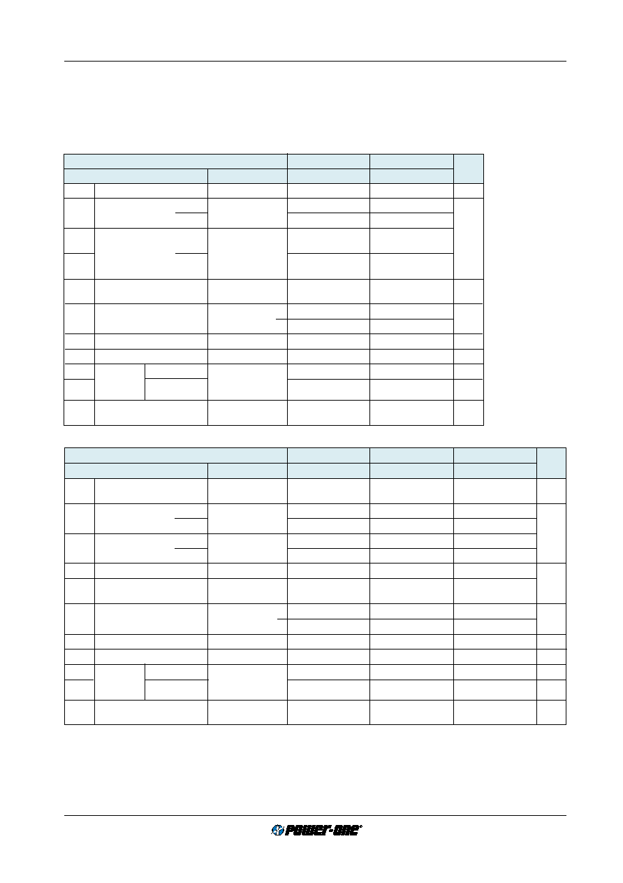
Electrical Output Data
General conditions:
– TA = 25
°C, unless T
C is specified
– Shutdown pin left open-circuit (not connected)
– Trim not connected
Table 6a: Output data for single (main) output.
Output
3.3 V
5.1 V
Characteristics
Conditions
min
typ
max
min
typ
max
Unit
Uo
Output voltage
Ui nom, Io = 0.5 Io nom
3.28
3.32
5.07
5.13
V DC
Io nom
Output current
20 IMX
Ui min...Ui max
3.5
2.9
A
40 IMX
4.25
3.4
Io1L
Current limit 1
20 IMX
Ui nom, TC = 25°C
5.5
4.2
Io2L
Uo1 = 93% Uo nom
Io1L
40 IMX
6.1
4.6
Io2L
DUo U
Line/load regulation
Ui min...Ui max,
±1
±1%
Io = (0.05...1) Io nom
uo1/2
Output voltage noise
Ui min...Ui max
2
70
80
mVpp
Io = Io nom
3
40
Uo L
Output overvoltage limit. 4
115
130
115
130
%
Co ext
Admissible capacitive load
4000
2700
F
uo d
Dynamic
Voltage deviat.
Ui nom
±250
mV
td
load
Recovery time
Io nom 1/2 Io nom
11
ms
regulation
IEC/EN 61204
aUo
Temperature coefficient
Ui min...Ui max
±0.02
%/K
DUo/DTC
Io = 0.1...1 Io nom
Table 6b: Output data for double output power trains.
Output
2
××××× 5 V
2
××××× 12 V
2
××××× 15 V
Characteristics
Conditions
min
typ
max
min
typ
max
min
max
Unit
Uo1
Output voltage
Ui nom
4.95
5.05
11.88
12.12
14.85
15.15
V DC
Uo2
Io = 0.5 Io nom
4.94
5.06
11.86
12.14
14.82
15.18
Io nom
Output current
20 IMX
Ui min...Ui max
2
× 1.35
2
× 0.65
2
× 0.55
A
40 IMX
2
× 1.4
2
× 0.70
2
× 0.60
IoL
Current limit 1
20 IMX
Ui nom, TC = 25°C
3.5
1.8
1.5
40 IMX
Uo = 93% Uo nom
3.7
2.0
1.6
DUo U
Line regulation
Ui min...Ui max, Io nom
±1
±1%
DUo l
Load regulation
Ui nom
±3
Io = (0.1...1) Io nom
uo1/2
Output voltage noise
Ui min...Ui max
2
80
120
150
mVpp
Io = Io nom
3
40
60
70
Uo L
Output overvoltage limit. 4
Min. load 1%
115
130
115
130
115
130
%
Co ext
Admissible capacitive load
4000
470
330
F
uo d
Dynamic
Voltage deviat.
Ui nom
±250
±400
±450
mV
td
load
Recovery time
Io nom 1/2 Io nom
11
1
ms
regulation
aUo
Temperature coefficient
Ui min...Ui max
±0.02
%/K
DUo/DTC
Io = 0.1...1 Io nom
1 The current limit is primary side controlled. In the event of a sustained overload condition the thermal protection may cause the unit to
shutdown (restart on cool-down).
2 BW = 20 MHz
3 Measured with a probe according to EN 61204
4 The overvoltage protection is via a primary side second regulation loop, not tracking with Trim control.
相關(guān)PDF資料 |
PDF描述 |
|---|---|
| 20IMX35-D05D12-9Z | 4-OUTPUT 35 W DC-DC REG PWR SUPPLY MODULE |
| 40IMX35-D05D12-9Z | 4-OUTPUT 35 W DC-DC REG PWR SUPPLY MODULE |
| 20IMX7-24-8C2 | 1-OUTPUT 6.2 W DC-DC REG PWR SUPPLY MODULE |
| 20KP120 | 20000 W, UNIDIRECTIONAL, SILICON, TVS DIODE |
| 21-033425-201 | CIRCULAR ADAPTER |
相關(guān)代理商/技術(shù)參數(shù) |
參數(shù)描述 |
|---|---|
| 20IMX35-05D12-9 | 制造商:POWER-ONE 制造商全稱:Power-One 功能描述:35 Watt DC-DC Converters |
| 20IMX35-05D15-9 | 制造商:POWER-ONE 制造商全稱:Power-One 功能描述:35 Watt DC-DC Converters |
| 20IMX35-12-12-9 | 制造商:POWER-ONE 制造商全稱:Power-One 功能描述:35 Watt DC-DC Converters |
| 20IMX35-15-15-9 | 制造商:POWER-ONE 制造商全稱:Power-One 功能描述:35 Watt DC-DC Converters |
| 20IMX35D05D05-8 | 功能描述:DC/DC轉(zhuǎn)換器 35W (4x 5V) DC Input (8.4-36V) RoHS:否 制造商:Murata 產(chǎn)品: 輸出功率: 輸入電壓范圍:3.6 V to 5.5 V 輸入電壓(標(biāo)稱): 輸出端數(shù)量:1 輸出電壓(通道 1):3.3 V 輸出電流(通道 1):600 mA 輸出電壓(通道 2): 輸出電流(通道 2): 安裝風(fēng)格:SMD/SMT 封裝 / 箱體尺寸: |
發(fā)布緊急采購,3分鐘左右您將得到回復(fù)。