- 您現(xiàn)在的位置:買賣IC網(wǎng) > PDF目錄293740 > 1417H4A TRANSCEIVER, PDFO PDF資料下載
參數(shù)資料
| 型號: | 1417H4A |
| 元件分類: | 數(shù)字傳輸電路 |
| 英文描述: | TRANSCEIVER, PDFO |
| 文件頁數(shù): | 3/10頁 |
| 文件大小: | 189K |
| 代理商: | 1417H4A |
NetLight 1417G4A and 1417H4A
Data Sheet
ATM/SONET/SDH Transceivers
January 2000
2
Lucent Technologies Inc.
Absolute Maximum Ratings
Stresses in excess of the absolute maximum ratings can cause permanent damage to the device. These are abso-
lute stress ratings only. Functional operation of the device is not implied at these or any other conditions in excess
of those given in the operations sections of the data sheet. Exposure to absolute maximum ratings for extended
periods can adversely affect device reliability.
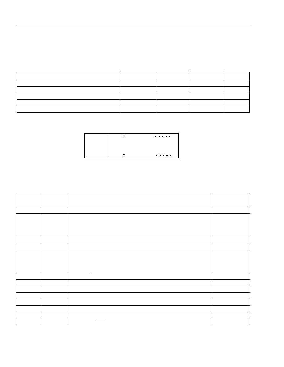
Pin Information
Figure 1. 1417G4A and 1714H4A Transceivers, 10-Pin Conguration, Top View
Parameter
Symbol
Min
Max
Unit
Supply Voltage
VCC
0
3.6
V
Operating Case Temperature Range
TC
–40
85
°C
Storage Case Temperature Range
Tstg
–40
85
°C
Lead Soldering Temperature/Time
—
250/10
°C/s
Operating Wavelength Range
λ
1.1
1.6
m
Table 1. Transceiver Pin Descriptions
Pin
Number
Symbol
Name/Description
Logic Family
Receiver
MS
Mounting Studs. The mounting studs are provided for transceiver
mechanical attachment to the circuit board. They may also provide an
optional connection of the transceiver to the equipment chassis
ground.
NA
1VEER
Receiver Signal Ground.
NA
2VCCR
Receiver Power Supply.
NA
3SD
Signal Detect.
Normal operation: logic one output.
Fault condition: logic zero output.
LVTTL
(1417H4A);
LVPECL
(1417G4A)
4
RD–
Received DATA Out.
LVPECL
5
RD+
Received DATA Out.
LVPECL
Transmitter
6VCCT
Transmitter Power Supply.
NA
7VEET
Transmitter Signal Ground.
NA
8TDIS
Transmitter Disable.
LVTTL
9
TD+
Transmitter DATA In.
LVPECL
10
TD–
Transmitter DATA In.
LVPECL
12345
10 9876
10-PIN MODULE - TOP VIEW
TX
RX
1-967.a
相關(guān)PDF資料 |
PDF描述 |
|---|---|
| 1417H4A | TRANSCEIVER, PDFO |
| 1418B2B | SPECIALTY TELECOM CIRCUIT, PSIP18 |
| 1418B2 | SPECIALTY TELECOM CIRCUIT, PSIP9 |
| 1430G5F | TRANSCEIVER, PDFO |
| 1430G5F | TRANSCEIVER, PDFO |
相關(guān)代理商/技術(shù)參數(shù) |
參數(shù)描述 |
|---|---|
| 1417H4A(NETLIGHT) | 制造商:AGERE 制造商全稱:AGERE 功能描述:ATM/SONET/SDH Transceivers |
| 1417H5 | 制造商:未知廠家 制造商全稱:未知廠家 功能描述:FIBER OPTIC TRANSCEIVER |
| 1417H5A | 制造商:AGERE 制造商全稱:AGERE 功能描述:NetLight 1417G5 and 1417H5-Type ATM/SONET/SDH Transceivers with Clock Recovery |
| 1417H5-TYPE(NETLIGHT) | 制造商:未知廠家 制造商全稱:未知廠家 功能描述:ATM/SONET/SDH Transceivers with Clock Recovery |
| 1417K4A | 制造商:NL 功能描述: |
發(fā)布緊急采購,3分鐘左右您將得到回復(fù)。