- 您現(xiàn)在的位置:買賣IC網(wǎng) > PDF目錄152674 > 118LAFT-12.800 (CTS CORP) OCXO, CLOCK, 12.8 MHz, HCMOS OUTPUT PDF資料下載
參數(shù)資料
| 型號: | 118LAFT-12.800 |
| 廠商: | CTS CORP |
| 元件分類: | OCXO, clock |
| 英文描述: | OCXO, CLOCK, 12.8 MHz, HCMOS OUTPUT |
| 封裝: | ROHS COMPLIANT, RESISTANCE WELD PACKAGE-14/5 |
| 文件頁數(shù): | 1/4頁 |
| 文件大小: | 102K |
| 代理商: | 118LAFT-12.800 |

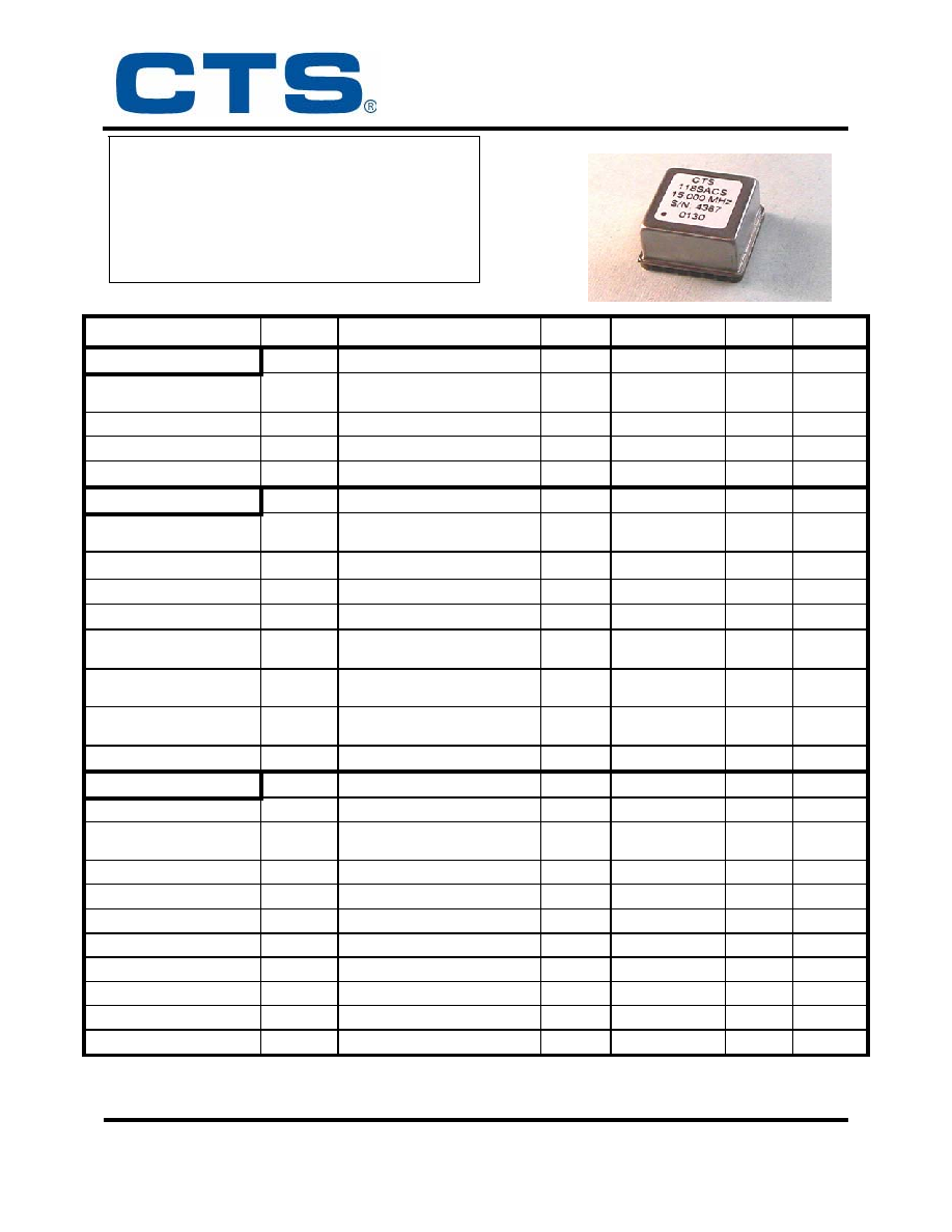
Model 118
1”x1” Stratum 3E OCXO
CTS 171 Covington Dr. Bloomingdale, IL 60108 800-757-6686 www.ctscorp.com
REVISION X3
Page 1 of 4
Electrical Characteristics
Parameter
Sym
Conditions
Min
Typical
Max
Unit
Power Requirements
Power Supply
Vcc
± 5%
3.135
4.75
3.30
5.0
3.465
5.25
Vdc
Turn-On Power
Pmax
Vcc = Max., Std. Load
3.5
4.0
W
Steady State Power
Pss
Vcc = Max, Std. Load @ +25
°C
1.5
W
Warm-Up Time
Twu
To meet full spec @ +25
°C
15
minutes
Frequency Stabilities
Center Frequency
fnom
10.0
10, 12.8, 16.384,
19.44, 20, 25, 26
38.88
MHz
Initial Tolerance
fcal
Ta = +25
°C (At time of Shipment)
± 0.2
± 0.5
ppm
Frequency vs. Temperature
f/Temp
Over Operating Temperature
± 6
± 8
ppb
Frequency vs. Voltage
f/Vcc
Vcc
± 5%
± 1
ppb
Frequency vs Time (Aging)
f/Time
per Day
20 years
± 1
± 1.5
ppb
ppm
24 Hour Holdover Stability
f/24Hr
Inclusive of Temperature, Supply
Variation and 24 hours Aging
± 8
± 10
ppb
Total Free-Running
Accuracy
f/Life
All Conditions for 20 years
(Reference to fnom)
± 2.1
ppm
Electrical Freq Adjust Option
f/Vc
Vc = 0 V to Vcc
±0.75
ppm
Waveform: HCMOS Output
Symmetry
Sym
@ 50% Level
40
50
60
%
Amplitude
Vo
Logic “1”
Logic “0”
0.9Vcc
0.1Vcc
V
Rise/Fall Times
tr, tf
20% to 80%
4
7
nSec
Load
RL
Output to Ground
10K
// 15pF
Sub-Harmonics
-25
dBc
Phase Noise
Offset = 1 Hz
-70
-60
dBc/Hz
10 Hz
-105
-95
dBc/Hz
100 Hz
-130
-125
dBc/Hz
1 KHz
-140
-130
dBc/Hz
10 KHz
-142
-135
dBc/Hz
Frequency Stability to Stratum 3E of GR-1244
Low Phase Jitter: <1pSec
+3.3Vdc or +5.0Vdc Operation
Precision Low Aging “SC” Cut Crystal
Through-Hole or Surface Mount Configuration
RoHS Compliant
相關PDF資料 |
PDF描述 |
|---|---|
| 118SAFT-19.440 | OCXO, CLOCK, 19.44 MHz, HCMOS OUTPUT |
| 118SBFT-10.000 | OCXO, CLOCK, 10 MHz, HCMOS OUTPUT |
| 118SBFS-FREQ | OCXO, CLOCK, 10 MHz - 38.88 MHz, HCMOS OUTPUT |
| 118SBFT-16.384 | OCXO, CLOCK, 16.384 MHz, HCMOS OUTPUT |
| 118LAFT-FREQ | OCXO, CLOCK, 10 MHz - 38.88 MHz, HCMOS OUTPUT |
相關代理商/技術參數(shù) |
參數(shù)描述 |
|---|---|
| 118-LB | 制造商:Thomas & Betts 功能描述:SWITCH BOX,NON-METAL |
| 118-LBP | 制造商:Thomas & Betts 功能描述: |
| 118MF100C | 制造商:ROSE 功能描述: |
| 118-N | 制造商:Thomas & Betts 功能描述: |
| 118-N0602-70 | 制造商:O-RINGS 功能描述: |
發(fā)布緊急采購,3分鐘左右您將得到回復。