- 您現(xiàn)在的位置:買賣IC網(wǎng) > PDF目錄298155 > 1056731-1 (Tyco Electronics) SMP/SMPM RF Connectors PDF資料下載
參數(shù)資料
| 型號: | 1056731-1 |
| 廠商: | Tyco Electronics |
| 元件分類: | 終端 |
| 英文描述: | SMP/SMPM RF Connectors |
| 中文描述: | SMP/SMPM 射頻連接器 |
| 文件頁數(shù): | 2/5頁 |
| 文件大小: | 246K |
| 代理商: | 1056731-1 |
153
Catalog 1307191
Dimensions are in millimeters
Dimensions are shown for
USA: 1-800-522-6752
South America: 55-11-2103-6000
Revised 3-07
and inches unless otherwise
reference purposes only.
Canada: 1-905-470-4425
Hong Kong: 852-2735-1628
specified. Values in brackets
Specifications subject
Mexico: 01-800-733-8926
Japan: 81-44-844-8013
www.tycoelectronics.com
are standard equivalents.
to change.
C. America: 52-55-1106-0803
UK: 44-8706-080-208
RF Coax Connectors
SMP Microminiature Push-On Coaxial Connectors (Continued)
General
Materials and Finishes
Housings and Center Contacts
Beryllium Copper per ASTM-B-196; gold plate over nickel plate
Dielectric
PTFE Fluorocarbon per ASTM-D-1457
Shrouds
Stainless steel per ASTM-A582 Type 303; passivate per ASTM-A380
Hermetic Seal
Glass bead
Electrical
Frequency Range
dc - 40.0 GHz
VSWR
1.10:1 Maximum dc - 23.0 GHz
1.15:1 Maximum 23.0 - 26.0 GHz
1.40:1 Maximum 26.0 - 40.0 GHz
Voltage Rating
335 Vrms maximum at sea level
Insertion Loss
0.10 f
√ (GHz) maximum
Insulation Resistance
5000 megohms minimum
Dielectric Withstanding Voltage
500 volts (VRMS minimum)
RF High Potential
325 volts (VRMS minimum) @ 5 MHz
Impedance
50 ohms nominal
RF Leakage
-80dB to 3 GHz, -65dB from 3 to 26.5 dB minimum
Contact Resistance
Initial center contact 6.0 milliohms maximum
Outer contact 2.0 milliohms maximum
Mechanical
Durability
100 mating cycles minimum
Radial Misalignment
±0.020 minimum
Axial Misalignment
.000/.010
Force to Engage
full detent
15.0 lbs. maximum
half detent
10.0 lbs. maximum
smooth bore
2.0 lbs. maximum
Force to Disengage
full detent
5.0 lbs. minimum
half detent
2.0 lbs. minimum
smooth bore
0.5 lbs. minimum
Center Contact Retention
1.5 lbs. minimum axial force
Environmental
Operating Temperature
-65°C to +165°C
Vibration
per mil-std-202, method 204, test condition D
Shock
per mil-std-202, method 213, test condition I
Thermal Shock
per mil-std-202, method 107, test condition B
Moisture Resistance
per MIL-STD-202 method 106, except step 7b shall be omitted. Resistance shall be 200 megohms
within 5 minutes after removal from humidity.
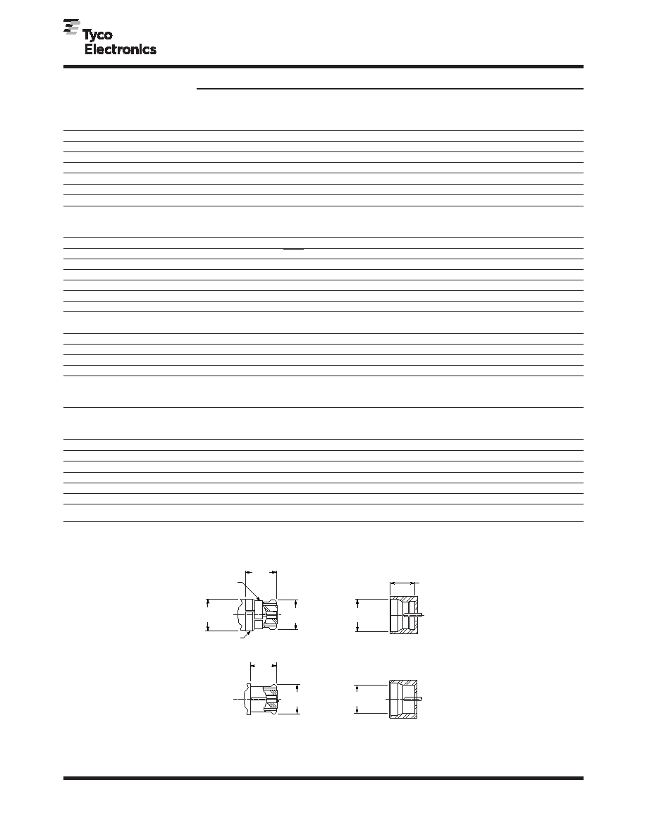
Specifications
Jack
Note: The U.S. Government (DESC) has determined that the above specified
interface dimensions are interchangeable and intermateble with Corning
Gilbert GPO Series RF Connectors.1
1
Per DESC drawing numbers 94007 and 94008, series SMP.
3.40
[.132]
Min.
3.43
[.135]
3.20 ± .050
[.125 ± .002]
2.80 ± .050
[.110 ± .002]
Dia.
2.8
[.112]
Min.
8.60 ± .076
[.142 ± .003]
Dia.
Max.
3.43
[.135]
Dia.
Max.
3.70
[.145]
Dia.
Max.
EMI Ring
Anti-Rock Ring
Full Detent
Bullet
Smooth Bore
Shroud
Interface Dimensions
GPO is a trademark of Corning Gilbert, Inc.
相關(guān)PDF資料 |
PDF描述 |
|---|---|
| 1056736-1 | SMP/SMPM RF Connectors |
| 1056744-1 | SMP/SMPM RF Connectors |
| 1056745-1 | SMP/SMPM RF Connectors |
| 1056750-1 | SMP/SMPM RF Connectors |
| 1056751-1 | SMP/SMPM RF Connectors |
相關(guān)代理商/技術(shù)參數(shù) |
參數(shù)描述 |
|---|---|
| 1056736-1 | 功能描述:RF 連接器 2998 5035 02 RoHS:否 制造商:Bomar Interconnect 產(chǎn)品:Connectors 射頻系列:BNC 型式:Jack (Female) 極性: 觸點電鍍:Gold 阻抗: 端接類型:Solder 主體類型:Straight Bulkhead 電纜類型: |
| 10-5674 | 制造商:CLAIRTRONIC 功能描述:TRANSFORMER 11VA 2 X 115V 2 X 6V |
| 1056740-1 | 功能描述:RF 連接器 HOUSING, SHROUD FULL DETENT SMP PASS RoHS:否 制造商:Bomar Interconnect 產(chǎn)品:Connectors 射頻系列:BNC 型式:Jack (Female) 極性: 觸點電鍍:Gold 阻抗: 端接類型:Solder 主體類型:Straight Bulkhead 電纜類型: |
| 1056741-1 | 功能描述:RF 連接器 HOUSING RF PASS RoHS:否 制造商:Bomar Interconnect 產(chǎn)品:Connectors 射頻系列:BNC 型式:Jack (Female) 極性: 觸點電鍍:Gold 阻抗: 端接類型:Solder 主體類型:Straight Bulkhead 電纜類型: |
| 1056742-1 | 制造商:TE Connectivity 功能描述:CONN ACC SHROUD - Bulk 制造商:TE Connectivity 功能描述:HOUSING, SHROUD, FULL DETENT, SMP, PASS |
發(fā)布緊急采購,3分鐘左右您將得到回復(fù)。