- 您現(xiàn)在的位置:買賣IC網(wǎng) > PDF目錄368691 > 100316QI (FAIRCHILD SEMICONDUCTOR CORP) Low Power Quad Differential Line Driver with Cut-Off PDF資料下載
參數(shù)資料
| 型號(hào): | 100316QI |
| 廠商: | FAIRCHILD SEMICONDUCTOR CORP |
| 元件分類: | 通用總線功能 |
| 英文描述: | Low Power Quad Differential Line Driver with Cut-Off |
| 中文描述: | 100K SERIES, 4-BIT DRIVER, COMPLEMENTARY OUTPUT, PQCC28 |
| 封裝: | PLASTIC, LCC-28 |
| 文件頁(yè)數(shù): | 3/6頁(yè) |
| 文件大?。?/td> | 56K |
| 代理商: | 100316QI |
3
www.fairchildsemi.com
1
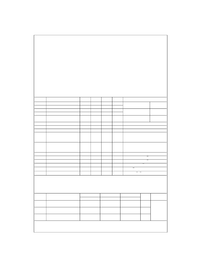
Absolute Maximum Ratings
(Note 1)
Recommended Operating
Conditions
Note 1:
The
“
Absolute Maximum Ratings
”
are those values beyond which
the safety of the device cannot be guaranteed. The device should not be
operated at these limits. The parametric values defined in the Electrical
Characteristics tables are not guaranteed at the absolute maximum rating.
The
“
Recommended Operating Conditions
”
table will define the conditions
for actual device operation.
Note 2:
ESD testing conforms to MIL-STD-883, Method 3015.
Commercial Version
DC Electrical Characteristics
(Note 3)
V
EE
=
4.2V to
5.7V, V
CC
=
V
CCA
=
GND, T
C
=
0
°
C to
+
85
°
C
Symbol
Parameter
Note 3:
The specified limits represent the
“
worst case
”
value for the parameter. Since these values normally occur at the temperature extremes, additional
noise immunity and guardbanding can be achieved by decreasing the allowable system operating ranges. Conditions for testing shown in the tables are cho-
sen to guarantee operation under
“
worst case
”
conditions.
AC Electrical Characteristics
V
EE
=
4.2V to
5.7V, V
CC
=
V
CCA
=
GND
Storage Temperature (T
STG
)
Maximum Junction Temperature (T
J
)
+
150
°
C
Pin Potential to Ground Pin (V
EE
)
Input Voltage (DC)
Output Current (DC Output HIGH)
ESD (Note 2)
65
°
C to
+
150
°
C
7.0V to 0.5V
V
EE
to
+
0.5V
100 mA
≥
2000V
Case Temperature (T
C
)
Commercial
Industrial
Supply Voltage (V
EE
)
0
°
C to
+
85
°
C
40
°
C to
+
85
°
C
5.7V to
4.2V
Min
Typ
Max
Units
Conditions
V
OH
V
OL
V
OHC
V
OLC
V
OLZ
Output HIGH Voltage
1025
1830
1035
955
1705
870
1620
mV
V
IN
=
V
IH
(Max)
or V
IL
(Min)
V
IN
=
V
IH
(Min)
or V
IL
(Max)
V
IN
=
V
IH
(Min)
or V
IL
(Max)
I
VBB
=
1 mA
Required for Full Output Swing
Loading with
25
to
2.0V
Loading with
25
to
2.0V
OE
=
LOW
Output LOW Voltage
Output HIGH Voltage
Output LOW Voltage
mV
mV
mV
1610
1950
Cut-Off LOW Voltage
mV
V
BB
V
DIFF
V
CM
V
IH
Output Reference Voltage
1380
150
V
CC
2.0
1320
1260
mV
Input Voltage Differential
Common Mode Voltage
Single-Ended
mV
V
V
CC
0.5
Guaranteed HIGH Signal for All
Input HIGH Voltage
1110
870
mV
Inputs (with one input tied to V
BB
)
V
BB
(Max)
+
V
DIFF
Guaranteed LOW Signal for All
V
IL
Single-Ended
Input LOW Voltage
1830
1530
mV
Inputs (with one input tied to V
BB
)
V
BB (Min)
V
DIFF
V
IN
=
V
IL
(Min)
V
IN
=
V
IH
(Max)
, D
1
=
V
BB
, D
1
=
V
IL
(Min)
V
IN
=
V
IH
(Max)
, D
1
=
V
BB
, D
1
=
V
IL
(Min)
V
IN
=
V
EE
, D
1
=
V
BB
, D
1
=
V
IL
(Min)
I
IL
I
IH
I
IHZ
I
CBO
I
EE
Input LOW Current
0.50
μ
A
Input HIGH Current D
N
Input HIGH Current OE
250
μ
A
360
μ
A
Input Leakage Current
10
μ
A
Power Supply Current, Normal
85
30
mA
D
1
=
V
BB
, D
1
=
V
IL
(Min)
I
EEZ
Power Supply Current, Cut-Off
152
75
mA
D
1
–
D
4
=
V
BB
, D
1
–
D
4
=
V
IL
(Min)
, OE
=
LOW
Symbol
Parameter
C
=
0
°
C
Min
T
C
=
+
25
°
C
Min
T
C
=
+
85
°
C
Min
Units
Conditions
Max
Max
Max
t
PLH
t
PHL
t
PZH
t
PHZ
t
TLH
t
THL
Propagation Delay
Data to Output
Propagation Delay
0.65
2.10
0.65
2.10
0.65
2.10
ns
Figures 1, 2
1.8
4.00
1.8
4.00
1.8
4.00
ns
OE to Output
Transition Time, D
n
to Q
n
20% to 80%, 80% to 20%
1.2
2.90
1.2
2.90
1.2
2.90
0.45
1.50
0.45
1.50
0.45
1.50
ns
相關(guān)PDF資料 |
PDF描述 |
|---|---|
| 100316QIX | Line Driver |
| 100319QC | Low Power Hex Line Driver with Cut-Off |
| 100319QI | Low Power Hex Line Driver with Cut-Off |
| 100319 | Low Power Hex Line Driver with Cut-Off |
| 100319QCX | Line Driver |
相關(guān)代理商/技術(shù)參數(shù) |
參數(shù)描述 |
|---|---|
| 100316QIX | 功能描述:緩沖器和線路驅(qū)動(dòng)器 Quad Diff Clock Drv RoHS:否 制造商:Micrel 輸入線路數(shù)量:1 輸出線路數(shù)量:2 極性:Non-Inverting 電源電壓-最大:+/- 5.5 V 電源電壓-最小:+/- 2.37 V 最大工作溫度:+ 85 C 安裝風(fēng)格:SMD/SMT 封裝 / 箱體:MSOP-8 封裝:Reel |
| 1003170000 | 制造商:Weidmuller 功能描述:CONN INSERT MALE SIZE HQ |
| 1003174-1 | 制造商:OMNIMOUNT 功能描述:UNISTRUT ADAPTER |
| 10031778-101 | 制造商:FCI 功能描述:4 ROW PF POWER ASSEMBLY - Trays |
| 1003180000 | 制造商:Weidmuller 功能描述:CONN INSERT FML SIZE HQ 制造商:Weidmuller 功能描述:HDC HQ 7 FC |
發(fā)布緊急采購(gòu),3分鐘左右您將得到回復(fù)。