- 您現(xiàn)在的位置:買賣IC網(wǎng) > PDF目錄245795 > 1-171370-2 (Tyco Electronics) Cluster Blocks PDF資料下載
參數(shù)資料
| 型號(hào): | 1-171370-2 |
| 廠商: | Tyco Electronics |
| 元件分類: | 終端 |
| 英文描述: | Cluster Blocks |
| 中文描述: | 成束接線盒 |
| 文件頁(yè)數(shù): | 26/102頁(yè) |
| 文件大?。?/td> | 3731K |
| 代理商: | 1-171370-2 |
第1頁(yè)第2頁(yè)第3頁(yè)第4頁(yè)第5頁(yè)第6頁(yè)第7頁(yè)第8頁(yè)第9頁(yè)第10頁(yè)第11頁(yè)第12頁(yè)第13頁(yè)第14頁(yè)第15頁(yè)第16頁(yè)第17頁(yè)第18頁(yè)第19頁(yè)第20頁(yè)第21頁(yè)第22頁(yè)第23頁(yè)第24頁(yè)第25頁(yè)當(dāng)前第26頁(yè)第27頁(yè)第28頁(yè)第29頁(yè)第30頁(yè)第31頁(yè)第32頁(yè)第33頁(yè)第34頁(yè)第35頁(yè)第36頁(yè)第37頁(yè)第38頁(yè)第39頁(yè)第40頁(yè)第41頁(yè)第42頁(yè)第43頁(yè)第44頁(yè)第45頁(yè)第46頁(yè)第47頁(yè)第48頁(yè)第49頁(yè)第50頁(yè)第51頁(yè)第52頁(yè)第53頁(yè)第54頁(yè)第55頁(yè)第56頁(yè)第57頁(yè)第58頁(yè)第59頁(yè)第60頁(yè)第61頁(yè)第62頁(yè)第63頁(yè)第64頁(yè)第65頁(yè)第66頁(yè)第67頁(yè)第68頁(yè)第69頁(yè)第70頁(yè)第71頁(yè)第72頁(yè)第73頁(yè)第74頁(yè)第75頁(yè)第76頁(yè)第77頁(yè)第78頁(yè)第79頁(yè)第80頁(yè)第81頁(yè)第82頁(yè)第83頁(yè)第84頁(yè)第85頁(yè)第86頁(yè)第87頁(yè)第88頁(yè)第89頁(yè)第90頁(yè)第91頁(yè)第92頁(yè)第93頁(yè)第94頁(yè)第95頁(yè)第96頁(yè)第97頁(yè)第98頁(yè)第99頁(yè)第100頁(yè)第101頁(yè)第102頁(yè)

3
Dimensions are in inches and
Dimensions are shown for
Technical Support
www.tycoelectronics.com
millimeters unless otherwise
reference purposes only.
USA: 1-800-522-6752
specified. Values in brackets
Specifications subject to change.
Canada: 1-905-475-6222
are metric equivalents.
Mexico: 01-800-733-8926
Standard MAG-MATE Terminals (Continued)
Magnet Wire Terminals and Termination Systems
Catalog 82221
Revised 10-02
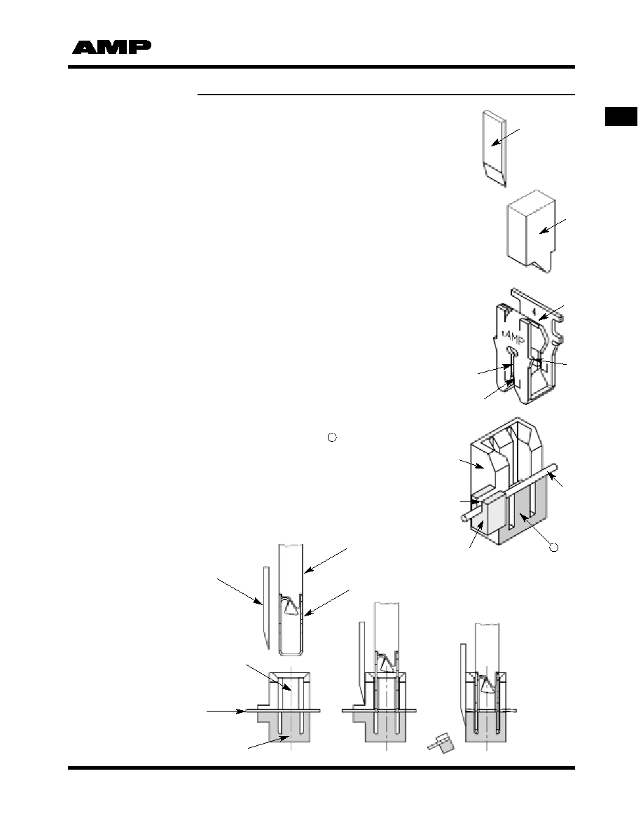
Standard
MAG-MATE
Terminals
Wire Cutter
This part cuts off the
excess magnet wire and
the wire support at the
front of the cavity.
Insertion Finger
The insertion finger is part
of the MAG-MATE
Inserter. It pushes the
terminal that was sheared
from the carrier strip
through the inserter “tube”
into the positioned cavity.
Contact
Various wire attachments
in three different sizes,
.187, .300, .500 cavity
height (see tables).
IDC Slot
In different sizes for
magnet wire diameters
from 34-12 AWG
[0.16-2.05 mm]. Strain
relief slots available
for high vibration
applications.
Stripping Shoulders
During the insertion
process, these shoulders
strip the film insulation
from the magnet wire in
four areas.
Standard MAG-MATE
Interconnection System
How the System Operates
Locking Barbs
Terminal retention is
secured in the cavity by
four locking barbs.
Plastic Cavity
Production must be in
accordance with
Tyco Electronics
Application Specifications.
Consulting
Tyco Electronics is
required for design in.
Cavity Slot for Wire
The width has to be in
accordance with the wire
size (see Application
Specification).
Magnet Wire
The magnet wire is
positioned in the “U” slot.
Wire Support Block
The block supports the
magnet wire during the
cutting process. The
magnet wire is cut flush
to the cavity front side.
Anvil
The anvil supports the
wire during the insertion
process.
Termination Sequence
A = Prepare
B = Insert
C = Finish
Post Trim Blade
Insertion Finger
Poke-In Contact
MAG-MATE Cavity
Magnet Wire
Support Anvil
A
B
C
11
11
相關(guān)PDF資料 |
PDF描述 |
|---|---|
| 1-172075-1 | Positive Lock Connectors |
| 1-172075-4 | Positive Lock Connectors |
| 1-172210-1 | Positive Lock Connectors |
| 1-172210-2 | Positive Lock Connectors |
| 1-172210-4 | Positive Lock Connectors |
相關(guān)代理商/技術(shù)參數(shù) |
參數(shù)描述 |
|---|---|
| 11713B | 制造商:Agilent Technologies 功能描述:11713B / 11713B Attenuator Switch Driver |
| 11713B-501 | 制造商:Agilent Technologies 功能描述:11713B / Viking connector to 9-pin D-Sub |
| 11713B-STD-101x2 | 制造商:Agilent Technologies 功能描述:Attenuator Switch Driver |
| 11713C-201 | 制造商:AGILENT TECHNOLOGIES, INC. 功能描述:12-PIN CONDUCTOR CABLE, BARE WIRE TO VIKING CONNECTOR |
| 11714 | 制造商:BARTON STORAGE SYSTEMS 功能描述:STORAGE BIN SIZE 1 BLUE |
發(fā)布緊急采購(gòu),3分鐘左右您將得到回復(fù)。