- 您現(xiàn)在的位置:買賣IC網(wǎng) > PDF目錄22763 > 012D440 DC FAN SPEED CONTROLLER 12V PDF資料下載
參數(shù)資料
| 型號: | 012D440 |
| 英文描述: | DC FAN SPEED CONTROLLER 12V |
| 中文描述: | 直流12V的風(fēng)扇調(diào)速器 |
| 文件頁數(shù): | 2/2頁 |
| 文件大?。?/td> | 168K |
| 代理商: | 012D440 |
33
CONTROL
RESOURCES
INCORPORATED
E-mail: sales@controlres.com s Web: www.controlres.com
Omni SD-DC — Installation & Operation
INSTALLATION
Mounting
To minimize EMI, mount the unit on a grounded
surface using a metal spacer at the mounting
hole that is surrounded by a conductive pad.
Sensor Selection
Sensors are shown on page 34. There is no polarity
consideration when connecting the sensor.
POWER
SUPPLY
Vs
+F
+
P
-
J1
-+
-
F
E
J3
S1
C
J2
SENSOR
R1 >= Va / 1 , kOhms
Va <= 30 VDC
V1 = Va, Above Trigger
V1 <= 0.4, Below Trigger
V1 = Va, Power Off to Unit
V1
Va
R1
FAN(S)
45
40
35
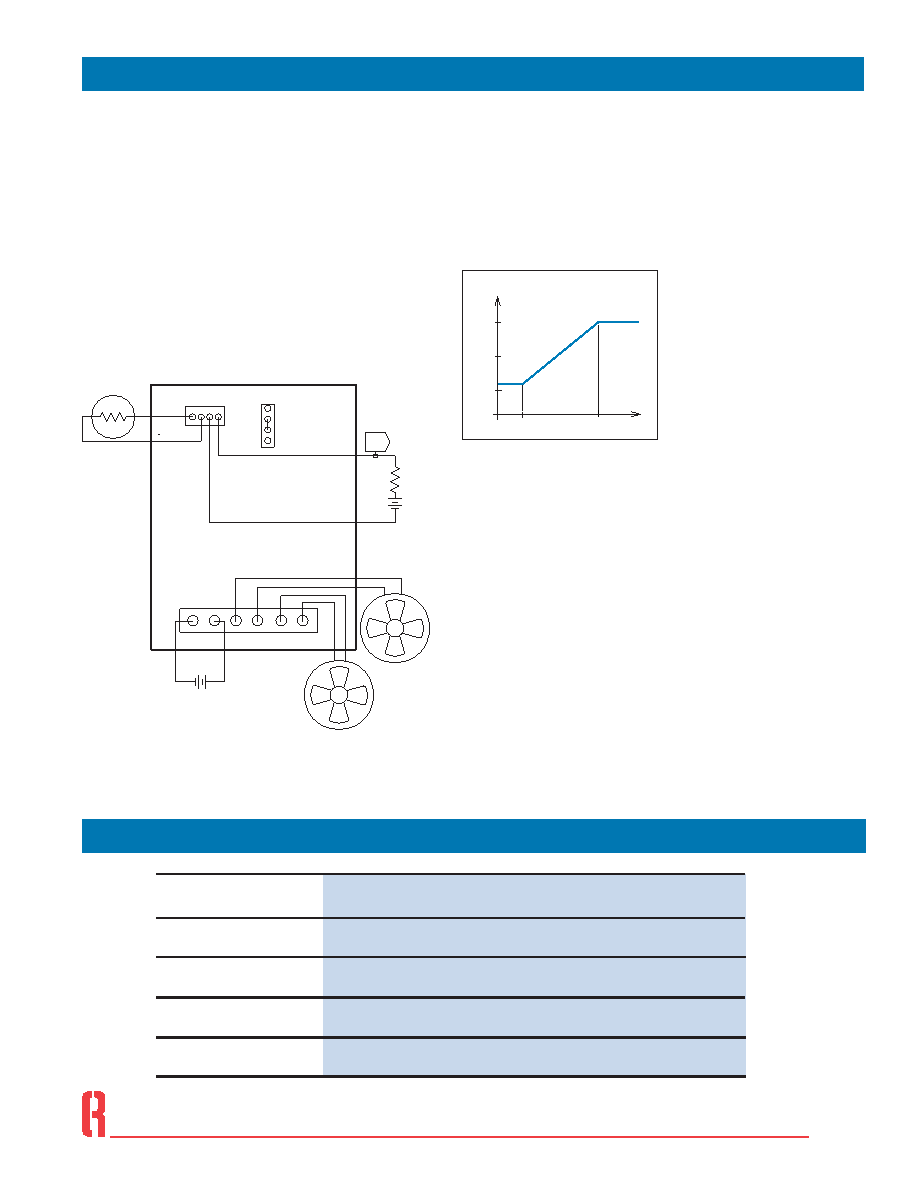
OPERATION
Fan Speed vs. Sensor Temperature
The relationship between fan speed, as a
percentage of full speed, and sensed temperature
is shown in Figure 2. Full speed occurs at the
Control Temperature (Tc).
Settings
Control Temperature (J2): Use this jumper to set
Control Temperature to 35°, 40°, or 45°C. Factory
setting is 40°C. If the P3 sensor is used, Control
Temperature settings are 74°, 80°, and 86°C.
Temperature Alarm Output (J3)
An over-temperature alarm output is provided
at header J3 to drive a logic circuit. Pins J3:C
and J3:E are internally connected to the collector
and emitter of a phototransistor, respectively.
This output is intended for connection to a
logic circuit.
Alarm Type:
Optically Isolated Phototransistor
Trigger:
10°C Above Control Temperature
Alarm States:
Conducting (Closed), Below Trigger,
Cut-Off (Open), Above Trigger,
Cut-Off (Open), Un-powered State
Max. Voltage:
30 VDC
Max. Current
1 mA DC
Suggested Connecting Hardware
Ref.
Desc.
Header on
Board1
Quantity
Description
Manufacturer1
Part Number1
J1
26-48-1065
J3
22-29-2041
1
6
1
4
1
H104 Hardware Pack
Housing
Terminal (tin)
Housing
Terminal (gold)
PCB Support
Aluminum Spacer
Screw, 6-32X 5/8
Nut, 6-32
Molex
Richco
09-50-8061
08-50-0106
22-01-3047
08-55-0102
CBS-4-19
ALSS6-2
1or equivalent
Connections/Jumpers
TC
C
- 3C
T C
Fan Speed vs. Sensor Temperature
100%
50%
Figure 2
Fan speed vs
sensor temperature
Figure 1
Wiring Diagram
J1 – Input Power and Fan Power
J2 – Control Temperature Setting
J3 – Sensor Input and Alarm Output
相關(guān)PDF資料 |
PDF描述 |
|---|---|
| 061-7BB@FREQ2 | CRYSTAL OSCILLATOR, CLOCK, 12.1 MHz - 24 MHz, TTL OUTPUT |
| 025.01.47 | SOCKET |
| 025.03.049 | *****GESTRICHEN***** |
| 025-03-50 | COUNTER SOCKET |
| 061-9BX@FREQ3 | CRYSTAL OSCILLATOR, CLOCK, 24 MHz - 65 MHz, TTL OUTPUT |
相關(guān)代理商/技術(shù)參數(shù) |
參數(shù)描述 |
|---|---|
| 012E61-31331-24 | 制造商:CORNING CABLE SYSTEMS 功能描述:12-FIBER FAN-OUT CABLE RISER RATED SMFE 1:0/1.0/0.75DB/KM 2.0MM |
| 012E68-31331-29 | 制造商:CORNING CABLE SYSTEMS 功能描述:CORNING CABLE 012E68-31331-29 |
| 012E81-33131-24 | 制造商:CORNING CABLE SYSTEMS 功能描述:12 STRAND, SINGLE MODE, TIGHT BUFFER |
| 012E88-33131-29 | 制造商:CORNING CABLE SYSTEMS 功能描述:12-F 8.3/125 TB PLENUM MIC 1.0/,75DB/KM 制造商:DigitHead Inc 功能描述:012E88-33131-29, CABLE, FIBER OPTIC, 9/125 SINGLE MODE, 12 STRANDS |
| 012EB5-14100A77 | 制造商:CORNING CABLE SYSTEMS 功能描述:12-FIBER SST-DROP CABLE SINGLE-JACKET/SINGLE-ARMOR |
發(fā)布緊急采購,3分鐘左右您將得到回復(fù)。