- 您現(xiàn)在的位置:買賣IC網(wǎng) > PDF目錄299933 > ST24C04R (意法半導(dǎo)體) Serial 4K (512 x 8) EEPROM(串行4K EEPROM) PDF資料下載
參數(shù)資料
| 型號: | ST24C04R |
| 廠商: | 意法半導(dǎo)體 |
| 英文描述: | Serial 4K (512 x 8) EEPROM(串行4K EEPROM) |
| 中文描述: | 串行4K的(512 × 8)的EEPROM(4K的串行EEPROM中) |
| 文件頁數(shù): | 3/16頁 |
| 文件大?。?/td> | 163K |
| 代理商: | ST24C04R |
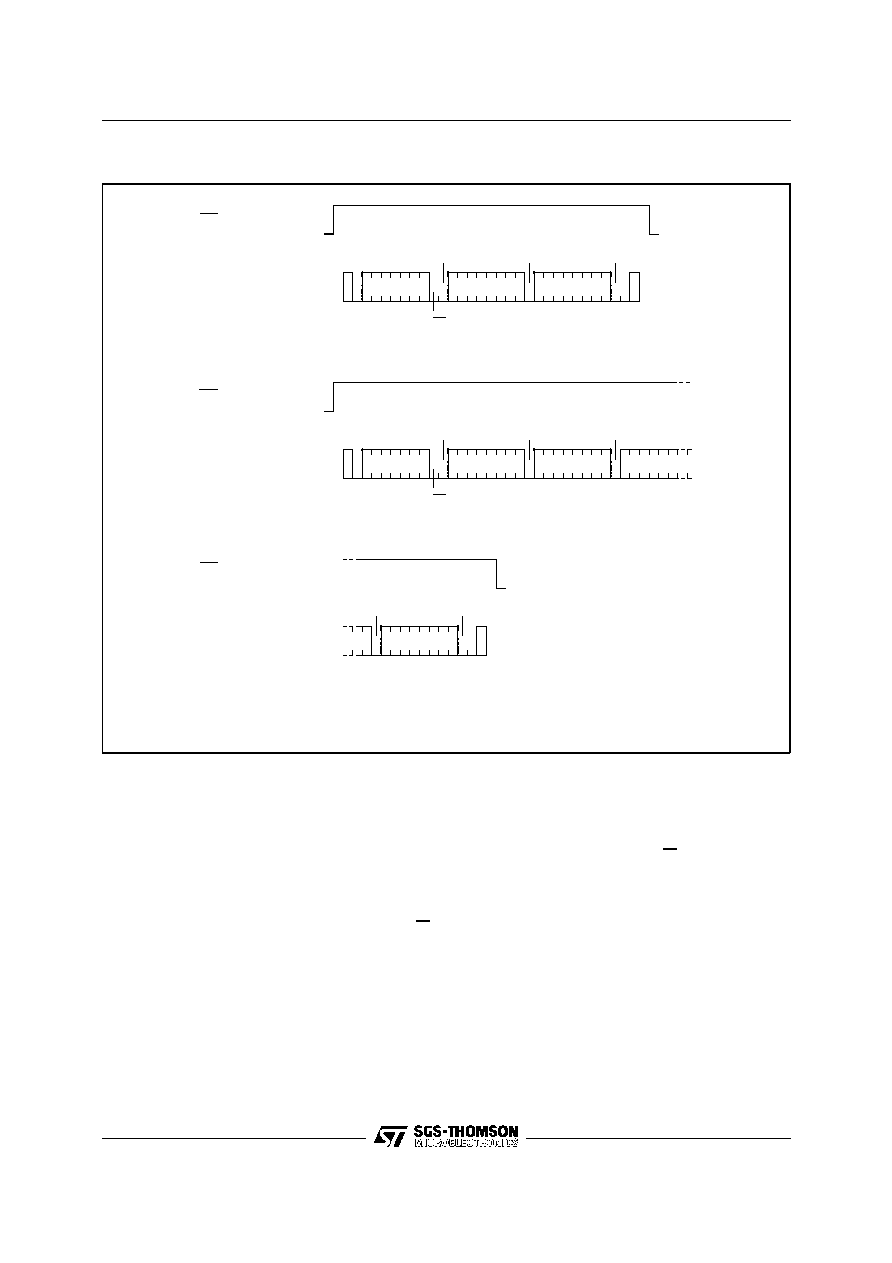
STOP
START
BYTE WRITE
DEV SEL
BYTE ADDR
DATA IN
WC
START
PAGE WRITE
DEV SEL
BYTE ADDR
DATA IN 1
WC
DATA IN 2
AI01101B
PAGE WRITE
(cont'd)
WC (cont'd)
STOP
DATA IN N
ACK
R/W
ACK
R/W
ACK
Figure 10. Write Modes Sequence with Write Control = 1 (ST24/25W04)
Read Operations
Read operations are independent of the state of the
MODE pin. On delivery, the memory content is set
at all "1’s" (or FFh).
Current Address Read. The memory has an inter-
nal byte address counter. Each time a byte is read,
this counter is incremented. For the Current Ad-
dress Read mode, following a START condition,
the master sends a memory address with the RW
bit set to ’1’. The memory acknowledges this and
outputs the byte addressed by the internal byte
address counter. This counter is then incremented.
The master does NOT acknowledge the byte out-
put, but terminates the transfer with a STOP con-
dition.
Random Address Read. A dummy write is per-
formed to load the address into the address
counter, see Figure 11. This is followed by another
START condition from the master and the byte
address is repeated with the RW bit set to ’1’. The
memory acknowledges this and outputs the byte
addressed. The master have to NOT acknowledge
the byte output, but terminates the transfer with a
STOP condition.
Sequential Read. This mode can be initiated with
either a Current Address Read or a Random Ad-
dress Read. However, in this case the master
DOES acknowledge the data byte output and the
memory continues to output the next byte in se-
quence. To terminate the stream of bytes, the
master must NOT acknowledge the last byte out-
11/16
ST24/25C04, ST24C04R, ST24/25W04
相關(guān)PDF資料 |
PDF描述 |
|---|---|
| ST25C08M1 | 1K X 8 SPI BUS SERIAL EEPROM, PDSO8 |
| ST280C04C1L | 960 A, 400 V, SCR, TO-200AB |
| ST280C04C2L | 960 A, 400 V, SCR, TO-200AB |
| ST280C04C2 | 960 A, 400 V, SCR, TO-200AB |
| ST280C04C3L | 960 A, 400 V, SCR, TO-200AB |
相關(guān)代理商/技術(shù)參數(shù) |
參數(shù)描述 |
|---|---|
| ST24C04RB1 | 制造商:未知廠家 制造商全稱:未知廠家 功能描述:I2C Serial EEPROM |
| ST24C04RB3 | 制造商:未知廠家 制造商全稱:未知廠家 功能描述:I2C Serial EEPROM |
| ST24C04RB5 | 制造商:未知廠家 制造商全稱:未知廠家 功能描述:I2C Serial EEPROM |
| ST24C04RB6 | 制造商:未知廠家 制造商全稱:未知廠家 功能描述:I2C Serial EEPROM |
| ST24C04RM1 | 制造商:未知廠家 制造商全稱:未知廠家 功能描述:I2C Serial EEPROM |
發(fā)布緊急采購,3分鐘左右您將得到回復(fù)。