- 您現(xiàn)在的位置:買賣IC網(wǎng) > PDF目錄299926 > SST48CF048-C1 24M X 16 FLASH 3.3V PROM CARD, 100 ns, XMA50 PDF資料下載
參數(shù)資料
| 型號: | SST48CF048-C1 |
| 元件分類: | PROM |
| 英文描述: | 24M X 16 FLASH 3.3V PROM CARD, 100 ns, XMA50 |
| 封裝: | CARD-50 |
| 文件頁數(shù): | 27/62頁 |
| 文件大?。?/td> | 1077K |
| 代理商: | SST48CF048-C1 |
第1頁第2頁第3頁第4頁第5頁第6頁第7頁第8頁第9頁第10頁第11頁第12頁第13頁第14頁第15頁第16頁第17頁第18頁第19頁第20頁第21頁第22頁第23頁第24頁第25頁第26頁當前第27頁第28頁第29頁第30頁第31頁第32頁第33頁第34頁第35頁第36頁第37頁第38頁第39頁第40頁第41頁第42頁第43頁第44頁第45頁第46頁第47頁第48頁第49頁第50頁第51頁第52頁第53頁第54頁第55頁第56頁第57頁第58頁第59頁第60頁第61頁第62頁
Data Sheet
CompactFlash Card
SST48CF008 / 016 / 024 / 032 / 048 / 064 / 096 / 128 / 192 / 256
33
2002 Silicon Storage Technology, Inc.
S71125-03-000
2/02
375
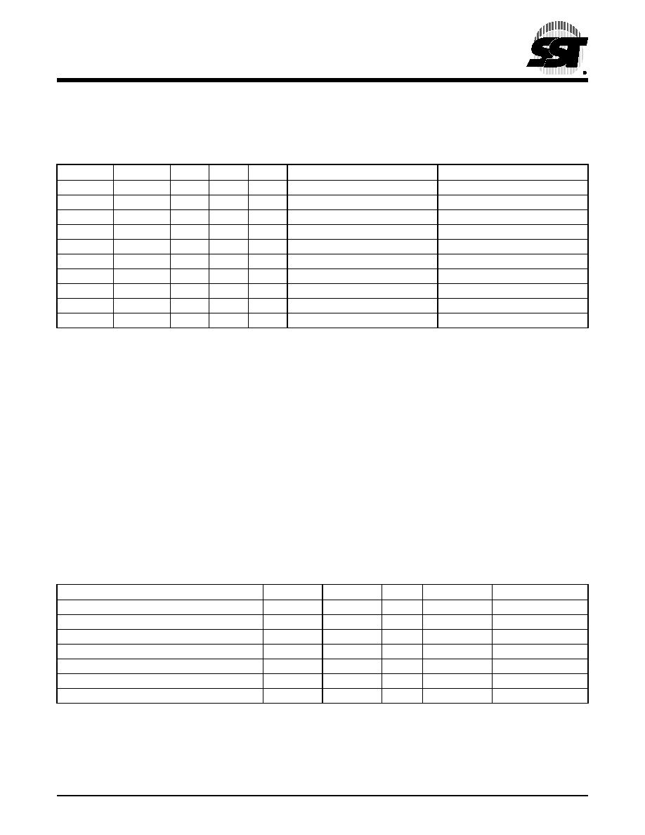
3.1.4 True IDE Mode Addressing
When the CompactFlash card is configured in the True IDE mode, the I/O decoding is as follows:
3.1.5 CF-ATA Registers
The following section describes the hardware registers used by the host software to issue commands to the Com-
pactFlash device. These registers are often collectively referred to as the “task file.”
Note: In accordance with the PCMCIA specification: each of the registers below which is located at an odd offset
address may be accessed at its normal address and also the corresponding even address (normal address
-1) using data bus lines (D15-D8) when -CE1 is high and -CE2 is low unless -IOIS16 is high (not asserted)
and an I/O cycle is being performed.
3.1.5.1 Data Register (Address - 1F0H[170H];Offset 0,8,9)
The Data register is a 16 bit register, and it is used to transfer data blocks between the CompactFlash card data
buffer and the Host. This register overlaps the Error register. The table below describes the combinations of data
register access and is provided to assist in understanding the overlapped Data register and Error/Feature register
rather than to attempt to define general PCMCIA word and byte access modes and operations. See the PCMCIA
PC Card Standard Release 2.0 for definitions of the Card Accessing Modes for I/O and Memory cycles.
Note: Because of the overlapped registers, access to the 1F1H, 171H or offset 1 are not defined for word (-CE2=0
and -CE1=0) operations. These accesses are treated as accesses to the Word Data register. The duplicated
registers at offsets 8, 9 and DH have no restrictions on the operations that can be performed by the socket.
TABLE
3-5: TRUE IDE MODE I/O DECODING
-CE2
-CE1
A2
A1
A0
-IORD=0
-IOWR=0
1
0
RD Data
WR Data
1
0
1
Error register
Features
1
0
1
0
Sector Count
1
0
1
Sector No.
1
0
1
0
Cylinder Low
1
0
1
0
1
Cylinder High
1
0
1
0
Select Card/Head
1
0
1
Status
Command
0
1
0
Alt Status
Device Control
0
1
Drive Address
Reserved
T3-5.0 375
Data Register
CE2-
CE1-
A0
Offset
Data Bus
Word Data Register
0
X
0,8,9
D15-D0
Even Data Register
1
0
0,8
D7-D0
Odd Data Register
1
0
1
9
D7-D0
Odd Data Register
0
1
X
8,9
D15-D8
Error / Feature Register
1
0
1
1, DH
D7-D0
Error / Feature Register
0
1
X
1
D15-D8
Error / Feature Register
0
X
DH
D15-D8
相關PDF資料 |
PDF描述 |
|---|---|
| SST49LF008C-33-4C-NHE | 1M X 8 FLASH 3V PROM, 11 ns, PQCC32 |
| SSU-131MAT | SLIDE SWITCH, SP3T, LATCHED, 0.3A, 4VDC, SURFACE MOUNT-RIGHT ANGLE |
| SSU-121ART | SLIDE SWITCH, SPDT, LATCHED, 0.3A, 4VDC, SURFACE MOUNT-RIGHT ANGLE |
| SSW-102-22-F-D-VS | 4 CONTACT(S), FEMALE, STRAIGHT TWO PART BOARD CONNECTOR, SURFACE MOUNT, SOCKET |
| SSW-102-22-F-S-VS | 2 CONTACT(S), FEMALE, STRAIGHT TWO PART BOARD CONNECTOR, SURFACE MOUNT, SOCKET |
相關代理商/技術參數(shù) |
參數(shù)描述 |
|---|---|
| SST48CF064 | 制造商:SST 制造商全稱:Silicon Storage Technology, Inc 功能描述:CompactFlash Card |
| SST48CF064-C1 | 制造商:SST 制造商全稱:Silicon Storage Technology, Inc 功能描述:CompactFlash Card |
| SST48CF096 | 制造商:SST 制造商全稱:Silicon Storage Technology, Inc 功能描述:CompactFlash Card |
| SST48CF096-C1 | 制造商:SST 制造商全稱:Silicon Storage Technology, Inc 功能描述:CompactFlash Card |
| SST48CF128 | 制造商:SST 制造商全稱:Silicon Storage Technology, Inc 功能描述:CompactFlash Card |
發(fā)布緊急采購,3分鐘左右您將得到回復。