- 您現(xiàn)在的位置:買賣IC網(wǎng) > PDF目錄372198 > SP705EP Low Power Microprocessor Supervisory Circuits PDF資料下載
參數(shù)資料
| 型號: | SP705EP |
| 英文描述: | Low Power Microprocessor Supervisory Circuits |
| 中文描述: | 低功耗微處理器監(jiān)控電路 |
| 文件頁數(shù): | 12/18頁 |
| 文件大小: | 197K |
| 代理商: | SP705EP |
SP705DS/09
SP705 Low Power Microprocessor Supervisory Circuits
Copyright 2000 Sipex Corporation
12
sensitivity to high-frequency noise on the
line being monitored. RESET can be used to
monitor voltages other than the +5V V
CC
line. Connect PFO to MR to initiate a RESET
pulse when PFI drops below 1.25V.
Figure 17
shows the
SP705/706/707/708
configured to
assert RESET when the +5V supply falls below
the RESET threshold, or when the +12V supply
falls below approximately 11V.
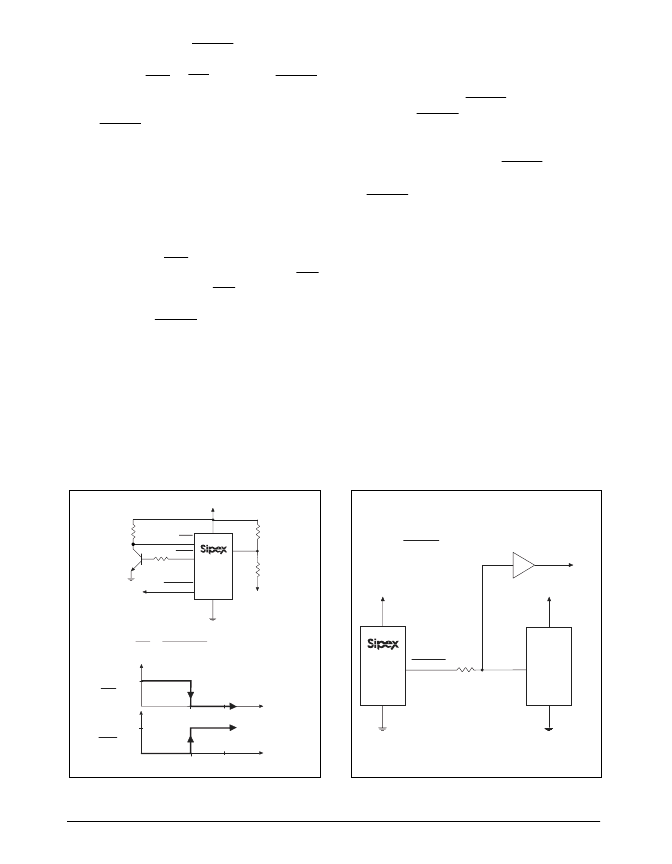
Monitoring a Negative Voltage Supply
The power-fail comparator can also monitor a
negative supply rail, shown in
Figure 18
. When
the negative rail is good (a negative voltage of
large magnitude), PFO is LOW. By adding the
resistors and transistor as shown, a HIGH PFO
triggers RESET. As long as PFO remains HIGH,
the
SP705-708/813L/813M
will keep RESET
asserted (where RESET = LOW and RESET =
HIGH). Note that this circuit's accuracy de-
pends on the PFI threshold tolerance, the V
CC
line, and the resistors.
Figure 18. Monitoring a Negative Voltage Supply
Figure 19. Interfacing to Microprocessors with
Bidirectional RESET I/O for the SP705/706/707/708
Interfacing to mPs with Bidirectional
RESET Pins
μ
Ps with bidirectional RESET pins, such as the
Motorola 68HC11 series, can contend with the
SP705/706/707/708
RESET output. If, for
example, the RESET output is driven HIGH and
the
μ
P wants to pull it LOW, indeterminate
logic levels may result. To correct this, connect
a 4.7K
resistor between the RESET output and
the
μ
P reset I/O, as shown if
Figure 19
. Buffer
the RESET output to other system components.
V
CC
+5V
GND
V
CC
+5V
GND
RESET
RESET
4.7K
μ
P
Buffered RESET connects to System Components
PFI
PFO
R
2
R
1
V
CC
+5V
GND
PFO
V-
+5V
V
TRIP
0V
0V
5.0 - 1.25
1.25 - V
TRIP
R
1
R
2
V-
=
100K
100K
RESET
to
μ
P
2N3904
, V
TRIP
< 0
V-
MR
0V
+5V
MR
相關PDF資料 |
PDF描述 |
|---|---|
| SP705EU | Low Power Microprocessor Supervisory Circuits |
| SP706CN | Low Power Microprocessor Supervisory Circuits |
| SP706CP | Low Power Microprocessor Supervisory Circuits |
| SP706CU | Low Power Microprocessor Supervisory Circuits |
| SP706EN | Low Power Microprocessor Supervisory Circuits |
相關代理商/技術參數(shù) |
參數(shù)描述 |
|---|---|
| SP705EP-L | 制造商:Rochester Electronics LLC 功能描述: 制造商:Exar Corporation 功能描述: |
| SP705EP-L/TR | 制造商:EXAR 制造商全稱:EXAR 功能描述:Low Power Microprocessor Supervisory Circuits |
| SP705EU | 制造商:SIPEX 制造商全稱:Sipex Corporation 功能描述:Low Power Microprocessor Supervisory Circuits |
| SP705EU-L/TR | 制造商:EXAR 制造商全稱:EXAR 功能描述:Low Power Microprocessor Supervisory Circuits |
| SP706 | 制造商:EXAR 制造商全稱:EXAR 功能描述:Low Power Microprocessor Supervisory Circuits |
發(fā)布緊急采購,3分鐘左右您將得到回復。