- 您現(xiàn)在的位置:買賣IC網(wǎng) > PDF目錄299877 > S1C60L09D 4-BIT, MROM, 0.08 MHz, MICROCONTROLLER, UUC70 PDF資料下載
參數(shù)資料
| 型號(hào): | S1C60L09D |
| 元件分類: | 微控制器/微處理器 |
| 英文描述: | 4-BIT, MROM, 0.08 MHz, MICROCONTROLLER, UUC70 |
| 封裝: | DIE-70 |
| 文件頁數(shù): | 37/62頁 |
| 文件大?。?/td> | 476K |
| 代理商: | S1C60L09D |
第1頁第2頁第3頁第4頁第5頁第6頁第7頁第8頁第9頁第10頁第11頁第12頁第13頁第14頁第15頁第16頁第17頁第18頁第19頁第20頁第21頁第22頁第23頁第24頁第25頁第26頁第27頁第28頁第29頁第30頁第31頁第32頁第33頁第34頁第35頁第36頁當(dāng)前第37頁第38頁第39頁第40頁第41頁第42頁第43頁第44頁第45頁第46頁第47頁第48頁第49頁第50頁第51頁第52頁第53頁第54頁第55頁第56頁第57頁第58頁第59頁第60頁第61頁第62頁
CHAPTER 4: PERIPHERAL CIRCUITS AND OPERATION (Stopwatch Timer)
36
EPSON
S1C60N09 TECHNICAL MANUAL
4.8.4 I/O memory of stopwatch timer
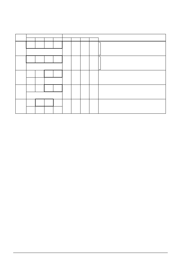
Table 4.8.4.1 shows the stopwatch timer control bits and their addresses.
Table 4.8.4.1 Control bits of stopwatch timer
Address
Comment
D3
D2
Register
D1
D0
Name
Init 1
10
071H
SWL3
SWL2
SWL1
SWL0
R
SWL3
SWL2
SWL1
SWL0
0
MSB
Stopwatch timer 1/100 sec data (BCD)
LSB
072H
SWH3
SWH2
SWH1
SWH0
R
SWH3
SWH2
SWH1
SWH0
0
MSB
Stopwatch timer 1/10 sec data (BCD)
LSB
076H
HLMOD
0
EISWIT1 EISWIT0
R/W
R
R/W
HLMOD
0 3
EISWIT1
EISWIT0
0
– 2
0
Heavy load
–
Enable
Normal
–
Mask
Heavy load protection mode register
Unused
Interrupt mask register (stopwatch 1 Hz)
Interrupt mask register (stopwatch 10 Hz)
07EH
TMRST SWRUN SWRST
IOC0
WR/W
TMRST3
SWRUN
SWRST3
IOC0
Reset
0
Reset
0
Reset
Run
Reset
Output
–
Stop
–
Input
Clock timer reset
Stopwatch timer Run/Stop
Stopwatch timer reset
I/O control register 0 (P00–P03)
07AH
0
IK0
SWIT1
SWIT0
R
0 3
IK0 4
SWIT1 4
SWIT0 4
– 2
0
–
Yes
–
No
Unused
Interrupt factor flag (K00–K03)
Interrupt factor flag (stopwatch 1 Hz)
Interrupt factor flag (stopwatch 10 Hz)
1
2
Initial value at initial reset
Not set in the circuit
3
4
Always "0" being read
Reset (0) immediately after being read
SWL0–SWL3: 1/100 sec stopwatch timer (071H)
Data (BCD) of the 1/100 sec column of the stopwatch timer can be read. These four bits are read-only, and
cannot be written.
After an initial reset, the timer data is set to "0H".
SWH0–SWH3: 1/10 sec stopwatch timer (072H)
Data (BCD) of the 1/10 sec column of the stopwatch timer can be read. These four bits are read-only, and
cannot be written.
After an initial reset, the timer data is set to "0H".
EISWIT0, EISWIT1: Interrupt mask registers (076HD0, D1)
These registers mask the stopwatch timer interrupt.
When "1" is written: Enabled
When "0" is written: Masked
Reading: Valid
The interrupt mask registers (EISWIT0, EISWIT1) are used to mask the 10 Hz and 1 Hz interrupts,
respectively.
After an initial reset, these registers are both set to "0".
SWIT0, SWIT1: Interrupt factor flags (07AHD0, D1)
These flags indicate the status of the stopwatch timer interrupt.
When "1" is read: Interrupt has occurred
When "0" is read: Interrupt has not occurred
Writing: Invalid
The interrupt factor flags (SWIT0, SWIT1) correspond to the 10 Hz and 1 Hz interrupts, respectively. With
these flags, the software can determine whether a stopwatch timer interrupt has occurred. However,
regardless of the interrupt mask register setting, these flags are set to "1" by the timer overflow.
They are reset by reading with the software.
相關(guān)PDF資料 |
PDF描述 |
|---|---|
| S1C63358F | 4-BIT, MROM, 4.1 MHz, MICROCONTROLLER, PQFP100 |
| S1D13503F00A | 1024 X 768 PIXELS CRT OR FLAT PNL GRPH DSPL CTLR, PQFP100 |
| S1DGPC | SLIDE SWITCH, SPDT, LATCHED, 0.05A, 48VDC, THROUGH HOLE-STRAIGHT |
| S1F | 1.2 A, 50 V, SCR, TO-92 |
| S2A | 1.5 A, 100 V, SCR, TO-92 |
相關(guān)代理商/技術(shù)參數(shù) |
參數(shù)描述 |
|---|---|
| S1C60L16 | 制造商:EPSON 制造商全稱:EPSON 功能描述:4-bit Single Chip Microcomputer |
| S1C60N05 | 制造商:EPSON 制造商全稱:EPSON 功能描述:4-bit Single Chip Microcomputer |
| S1C60N08 | 制造商:EPSON 制造商全稱:EPSON 功能描述:4-bit Single Chip Microcomputer |
| S1C60N16 | 制造商:EPSON 制造商全稱:EPSON 功能描述:4-bit Single Chip Microcomputer |
| S1C60R08 | 制造商:EPSON 制造商全稱:EPSON 功能描述:4-bit Single Chip Microcomputer |
發(fā)布緊急采購,3分鐘左右您將得到回復(fù)。