- 您現(xiàn)在的位置:買賣IC網(wǎng) > PDF目錄100796 > 7205J62ZQE12 (C K COMPONENTS INC) TOGGLE SWITCH, DPDT, MOMENTARY, 5A, 28VDC, PANEL MOUNT PDF資料下載
參數(shù)資料
| 型號: | 7205J62ZQE12 |
| 廠商: | C K COMPONENTS INC |
| 元件分類: | 開關(guān) |
| 英文描述: | TOGGLE SWITCH, DPDT, MOMENTARY, 5A, 28VDC, PANEL MOUNT |
| 封裝: | ROHS COMPLIANT |
| 文件頁數(shù): | 2/22頁 |
| 文件大?。?/td> | 2753K |
| 代理商: | 7205J62ZQE12 |
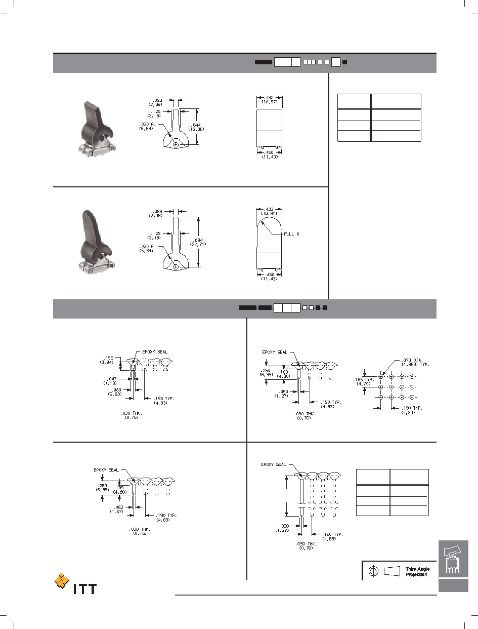
C&K 7000 Series
Miniature Rocker & Lever Handle Switches
ACTUATOR–PC MOUNT
TERMINATIONS
PC MOUNTING
Dim 'A'
SPDT thru 4PDT
Z3
QUICK CONNECT
W, W3, W5
WIRE WRAP
SPDT thru 4PDT
Not available with K, L or M contact materials.
Available actuators, see pages H-7 through H-13.
Not available with K, L or M contact materials. Available
actuators, see pages H-7 through H-13. Mating quick
connector available; order part number 530100000,
page H-23.
NOTE: Available actuators, see
pages H-7 through H-13.
NOTE: Available actuators, see pages H-7 through H-13.
Finish: Matte. Other colors, custom actuator
markings and legends available, consult
Customer Service Center.
NOTE: Some permissible actuator/termination
combinations may lack clearance between
actuator and PC board, and care must be
exercised to accommodate this condition.
Actuators available separately, see page H-22.
J60 & J90 actuators available with A (DP, 3P
models only), A3 (DP, 3P models only), AV2,
AV3, AW3 (DP, 3P models only) & V2-V61
terminations.
SPDT thru 4PDT
Z
SOLDER LUG
C
PC THRU-HOLE
J90
LEVER
J60
LEVER
ACTUATOR COLOR
ACTUATOR
2
BLACK
1
WHITE
3
RED
ACTUATOR
COLOR
OPTION
CODE
W
.750 (19,05)
W3
.425 (10,80)
W5
1.305 (33,15)
DIM ‘A’
OPTION
CODE
H–13
H
Rocker
Dimensions are shown: Inch (mm)
Specifications and dimensions subject to change
www.ittcannon.com
相關(guān)PDF資料 |
PDF描述 |
|---|---|
| 7207J1Z3GI1 | ROCKER SWITCH, DPDT, LATCHED AND MOMENTARY, 5A, 28VDC, PANEL MOUNT |
| 7207J1ZGI3 | ROCKER SWITCH, DPDT, LATCHED AND MOMENTARY, 5A, 28VDC, PANEL MOUNT |
| 7207J21CGE11 | TOGGLE SWITCH, DPDT, LATCHED AND MOMENTARY, 5A, 28VDC, THROUGH HOLE-STRAIGHT |
| 7208J11W3SI12 | ROCKER SWITCH, DPDT, LATCHED AND MOMENTARY, 5A, 28VDC, PANEL MOUNT |
| 7208J26W5KE11 | TOGGLE SWITCH, DPDT, LATCHED AND MOMENTARY, 0.02A, 20VDC, PANEL MOUNT |
相關(guān)代理商/技術(shù)參數(shù) |
參數(shù)描述 |
|---|---|
| 7205J62ZQE21 | 功能描述:搖臂開關(guān)與扳鈕開關(guān) RoHS:否 制造商:C&K Components 觸點(diǎn)形式: 開關(guān)功能: 電流額定值:50 mA 電壓額定值 AC: 電壓額定值 DC:30 V 功率額定值: 端接類型: 執(zhí)行器:Paddle 顏色: 安裝風(fēng)格:Panel 端子密封: 觸點(diǎn)電鍍: 照明:Not Illuminated 照明顏色: |
| 7205J62ZQE22 | 功能描述:搖臂開關(guān)與扳鈕開關(guān) RoHS:否 制造商:C&K Components 觸點(diǎn)形式: 開關(guān)功能: 電流額定值:50 mA 電壓額定值 AC: 電壓額定值 DC:30 V 功率額定值: 端接類型: 執(zhí)行器:Paddle 顏色: 安裝風(fēng)格:Panel 端子密封: 觸點(diǎn)電鍍: 照明:Not Illuminated 照明顏色: |
| 7205J62ZQE32 | 功能描述:搖臂開關(guān)與扳鈕開關(guān) RoHS:否 制造商:C&K Components 觸點(diǎn)形式: 開關(guān)功能: 電流額定值:50 mA 電壓額定值 AC: 電壓額定值 DC:30 V 功率額定值: 端接類型: 執(zhí)行器:Paddle 顏色: 安裝風(fēng)格:Panel 端子密封: 觸點(diǎn)電鍍: 照明:Not Illuminated 照明顏色: |
| 7205J64CQE3 | 功能描述:搖臂開關(guān)與扳鈕開關(guān) RoHS:否 制造商:C&K Components 觸點(diǎn)形式: 開關(guān)功能: 電流額定值:50 mA 電壓額定值 AC: 電壓額定值 DC:30 V 功率額定值: 端接類型: 執(zhí)行器:Paddle 顏色: 安裝風(fēng)格:Panel 端子密封: 觸點(diǎn)電鍍: 照明:Not Illuminated 照明顏色: |
| 7205J64WBE2 | 功能描述:搖臂開關(guān)與扳鈕開關(guān) RoHS:否 制造商:C&K Components 觸點(diǎn)形式: 開關(guān)功能: 電流額定值:50 mA 電壓額定值 AC: 電壓額定值 DC:30 V 功率額定值: 端接類型: 執(zhí)行器:Paddle 顏色: 安裝風(fēng)格:Panel 端子密封: 觸點(diǎn)電鍍: 照明:Not Illuminated 照明顏色: |
發(fā)布緊急采購,3分鐘左右您將得到回復(fù)。