- 您現(xiàn)在的位置:買賣IC網(wǎng) > PDF目錄374434 > MFL2805D (CRANE ELECTRONICS INC) DC/DC CONVERTERS 28 VOLT INPUT PDF資料下載
參數(shù)資料
| 型號(hào): | MFL2805D |
| 廠商: | CRANE ELECTRONICS INC |
| 元件分類: | 基準(zhǔn)電壓源/電流源 |
| 英文描述: | DC/DC CONVERTERS 28 VOLT INPUT |
| 中文描述: | 2-OUTPUT 50 W DC-DC REG PWR SUPPLY MODULE |
| 封裝: | HERMETIC SEALED PACKAGE-12 |
| 文件頁數(shù): | 3/8頁 |
| 文件大?。?/td> | 184K |
| 代理商: | MFL2805D |

3
MFL SERIES
65 WATT
DC/DC C
ONVERTERS
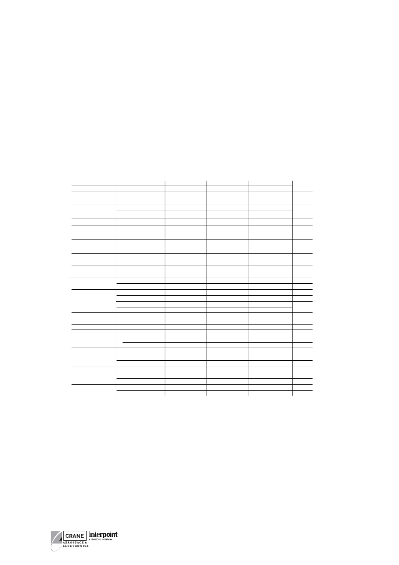
Electrical Characteristics: –55°C to +125°C Tc, 28 VDC Vin, 100% load, free run, unless otherwise specified.
DUAL OUTPUT MODELS
PARAMETER
OUTPUT VOLTAGE
MFL2805D
MIN
TYP
4.95
5.00
4.92
5.00
MFL2812D
MIN
TYP
11.88 12.00
11.82 12.00
MFL2815D
MIN
TYP
CONDITIONS
Tc = 25°C–V
OUT
MAX
5.05
5.08
MAX
12.12 14.85 15.00
12.18
14.77 15.00
MAX
15.15
15.23
UNITS
VDC
OUT
OUTPUT CURRENT
1
EACH OUTPUT
0
—
7
0
—
3.5
0
—
3.03
A
V
IN
= 16 TO 40 VDC
OUTPUT POWER
TOTAL OUTPUT
0
—
10
0
—
5
0
—
4.34
V
IN
= 16 TO 40 VDC
0
—
50
0
—
60
0
—
65
W
OUTPUT RIPPLE
VOLTAGE +/– V
OUT
LINE REGULATION
10 kHz - 2 MHz
—
50
100
—
50
120
—
50
150
mV p-p
+V
OUT
–V
OUT
+V
OUT
–V
OUT
—
0
50
—
0
50
—
0
50
mV
V
IN
= 16 TO 40 VDC
LOAD REGULATION
NO LOAD TO FULL
—
25
100
—
25
100
—
25
100
—
—
0
25
50
100
—
—
10
50
100
120
—
—
10
50
100
150
mV
CROSS REGULATION
Tc = 25°C
SEE NOTE 2
SEE NOTE 3
—
—
5
8
—
2
4
—
2
4
%
3
6
—
2
4
—
2
4
INPUT VOLTAGE
NO LOAD TO FULL
INPUT CURRENT
Tc = 25°C
CONTINUOUS
TRANSIENT
4
50 ms.
NO LOAD
FULL LOAD
INHIBITED - INH1
INHIBITED - INH2
16
0
—
—
—
—
28
—
50
—
9
35
40
50
120
16
0
—
—
—
—
28
—
50
—
9
35
40
50
100
2.80
14
70
16
0
—
—
—
—
28
—
50
—
9
35
40
50
100
3.00
14
70
VDC
V
mA
A
14
70
mA
INPUT RIPPLE
CURRENT
EFFICIENCY 25°C Tc
LOAD FAULT
5
Tc = 25°C
10 kHz - 10 MHz
BALANCED LOAD
POWER DISSIPATION
SHORT CIRCUIT
RECOVERY
50 %–100%– 50% LOAD
TRANSIENT
RECOVERY
6
16 – 40 – 16 V
IN
TRANSIENT
7
RECOVERY
6
DELAY
—
77
15
80
50
—
—
83
15
86
50
—
—
84
15
87
50
—
mA p-p
%
—
—
12.5
1.5
16
4.0
—
—
10
1.5
14
4.0
—
—
10
1.5
14
4.0
W
ms
STEP LOAD
RESPONSE ± V
OUT
—
250
350
—
450
600
—
500
600
mV pk
—
1.5
3.0
—
1.5
3.0
—
1.5
3.0
ms
STEP LINE
RESPONSE ± V
OUT
—
250
300
—
250
400
—
250
400
mV pk
—
—
200
3.5
300
6
—
—
200
3.5
300
6
—
—
200
3.5
300
6
μs
ms
START–UP
OVERSHOOT
—
0
25
—
0
50
—
0
50
mV p
Notes
1. Up to 70% of the total output power is available from either output providing
the opposite output is simultaneously carrying 30% of the total power.
2. Effect on the negative output under the following conditions:
+P
30% to 70%; –P
70% to 30%
3. Effect on the negative output under the following conditions:
+P
out
50%; –P
out
10% to 50%
4. Unit will shut down above approximately 45V but will be undamaged and will
restart when voltage drops into normal range.
5. Indefinite short circuit protection not guaranteed above 125°C case.
6. Recovery time is measured from application of the transient to point at which
Vout is within 1% of final value.
7. Transition time
≥
10 μs.
相關(guān)PDF資料 |
PDF描述 |
|---|---|
| MFL2805S | DC/DC CONVERTERS 28 VOLT INPUT |
| MFL2812D | DC/DC CONVERTERS 28 VOLT INPUT |
| MFL2812S | DC/DC CONVERTERS 28 VOLT INPUT |
| MFL2815D | DC/DC CONVERTERS 28 VOLT INPUT |
| MFL2815S | DC/DC CONVERTERS 28 VOLT INPUT |
相關(guān)代理商/技術(shù)參數(shù) |
參數(shù)描述 |
|---|---|
| MFL2805D/883 | 制造商:INTERPOINT 制造商全稱:INTERPOINT 功能描述:DC/DC CONVERTERS 28 VOLT INPUT |
| MFL2805D/ES | 制造商:CRANE 制造商全稱:CRANE 功能描述:MFL Single and Dual DC/DC Converters |
| MFL2805S | 制造商:INTERPOINT 制造商全稱:INTERPOINT 功能描述:Parallel operation with current share, 16 to 40 VDC input |
| MFL2805S/883 | 制造商:INTERPOINT 制造商全稱:INTERPOINT 功能描述:DC/DC CONVERTERS 28 VOLT INPUT |
| MFL2805S/ES | 制造商:CRANE 制造商全稱:CRANE 功能描述:MFL Single and Dual DC/DC Converters |
發(fā)布緊急采購,3分鐘左右您將得到回復(fù)。