- 您現(xiàn)在的位置:買賣IC網(wǎng) > PDF目錄292629 > SP6333EK1-L-S-I-A TOGGLE SWITCH, DP3T, MOMENTARY, 4A, 28VDC, PANEL MOUNT-THREADED PDF資料下載
參數(shù)資料
| 型號(hào): | SP6333EK1-L-S-I-A |
| 元件分類: | 開關(guān) |
| 英文描述: | TOGGLE SWITCH, DP3T, MOMENTARY, 4A, 28VDC, PANEL MOUNT-THREADED |
| 文件頁數(shù): | 6/7頁 |
| 文件大小: | 525K |
| 代理商: | SP6333EK1-L-S-I-A |
APEM
www.apem.com
A-83
12000X778 series
High performance toggle switches - threaded bushing 11,9 (15/32)
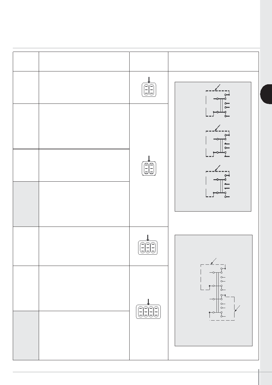
Positions and connections
A
FUNCTION
12146
12147
12148
12149
12148CT
12145
12144
12144-1R
12144-2R
12156
12166
12164
TERMINAL
IDENTIFICATION
WIRING FOR 3-WAY SWITCHES
(FUNCTION 4)
LEVER POSITION AND CONNECTIONS
I
II
III (Flat)
ON
-
ON
(1-3)-4
(1-3)-2
(5-7)-8
(5-7)-6
MOM
OFF
MOM
ON
OFF
MOM
ON
OFF
ON
MOM
OFF
ON
1-2
1-3
4-5
4-6
-
ON
MOM
1-2
1-3
4-5
4-6
ON
MOM
ON
MOM
ON
MOM
1-2
1-3
4-5
4-6
ON
-
ON
(1-3)-4
(1-3)-2
(5-7)-8
(5-7)-6
(9-11)-12
(9-11)-10
ON
-
ON
1A - 3A
1A - 2A
1C - 3C
1C - 2C
1E - 3E
1E - 2E
1G - 3G
1G - 2G
ON
1A - 2A
1A - 3A
1C - 2C
1C - 3C
1E - 2E
1E - 3E
1G - 2G
1G - 3G
External jumper (added by customer)
12164
12144
12144-1R
12144-2R
Flat
A
2
1
33
1
2
4
3-1
210
9-11
12
3
1
25
4
6
7-5
8
4
3-1
2
CE
G
A
2
1
33
1
2
4
3-1
210
9-11
12
3
1
25
4
6
7-5
8
4
3-1
2
A
2
1
33
1
2
4
3-1
210
9-11
12
3
1
25
4
6
7-5
8
4
3-1
2
CE
G
A
2
1
33
1
2
4
3-1
210
9-11
12
3
1
25
4
6
7-5
8
4
3-1
2
A
2
1
33
1
2
4
3-1
210
9-11
12
3
1
25
4
6
7-5
8
4
3-1
2
CE
G
A
2
1
33
1
2
4
3-1
210
9-11
12
3
1
25
4
6
7-5
8
4
3-1
2
A
2
1
33
1
2
4
3-1
210
9-11
12
3
1
25
4
6
7-5
8
4
3-1
2
CE
G
A
2
1
33
1
2
4
3-1
210
9-11
12
3
1
25
4
6
7-5
8
4
3-1
2
1
4
3
2
6
5
4
1
3
2
6
5
4
1
3
2
6
5
1A
2A
1C
1E
1G
3A
2C
3C
2E
3E
2G
3G
相關(guān)PDF資料 |
PDF描述 |
|---|---|
| SP6333EK1-L-S-H-C | TOGGLE SWITCH, DP3T, MOMENTARY, 4A, 28VDC, PANEL MOUNT-THREADED |
| SP6333EK1-L-R-H-A/TR | TOGGLE SWITCH, DP3T, MOMENTARY, 4A, 28VDC, PANEL MOUNT-THREADED |
| SP6333EK1-L-R-B-D | TOGGLE SWITCH, DP3T, MOMENTARY, 4A, 28VDC, PANEL MOUNT-THREADED |
| SP6333EK1-L-Z-G-C | TOGGLE SWITCH, DP3T, MOMENTARY, 4A, 28VDC, PANEL MOUNT-THREADED |
| SP6333EK1-L-Y-F-C/TR | TOGGLE SWITCH, DP3T, MOMENTARY, 4A, 28VDC, PANEL MOUNT-THREADED |
相關(guān)代理商/技術(shù)參數(shù) |
參數(shù)描述 |
|---|---|
| SP6334 | 制造商:SIPEX 制造商全稱:Sipex Corporation 功能描述:Quad レPower Supervisory Circuits with Manual Reset & Watchdog |
| SP6334EK1-L-V-I-B | 功能描述:監(jiān)控電路 Quad microPower 監(jiān)控電路 RoHS:否 制造商:STMicroelectronics 監(jiān)測電壓數(shù): 監(jiān)測電壓: 欠電壓閾值: 過電壓閾值: 輸出類型:Active Low, Open Drain 人工復(fù)位:Resettable 監(jiān)視器:No Watchdog 電池備用開關(guān):No Backup 上電復(fù)位延遲(典型值):10 s 電源電壓-最大:5.5 V 最大工作溫度:+ 85 C 安裝風(fēng)格:SMD/SMT 封裝 / 箱體:UDFN-6 封裝:Reel |
| SP6334EK1-L-V-I-B/TR | 功能描述:監(jiān)控電路 Quad Micropower w/ Manual Reset&Watchdg RoHS:否 制造商:STMicroelectronics 監(jiān)測電壓數(shù): 監(jiān)測電壓: 欠電壓閾值: 過電壓閾值: 輸出類型:Active Low, Open Drain 人工復(fù)位:Resettable 監(jiān)視器:No Watchdog 電池備用開關(guān):No Backup 上電復(fù)位延遲(典型值):10 s 電源電壓-最大:5.5 V 最大工作溫度:+ 85 C 安裝風(fēng)格:SMD/SMT 封裝 / 箱體:UDFN-6 封裝:Reel |
| SP6334EK1-L-X-J-C | 功能描述:監(jiān)控電路 Quad microPower 監(jiān)控電路 RoHS:否 制造商:STMicroelectronics 監(jiān)測電壓數(shù): 監(jiān)測電壓: 欠電壓閾值: 過電壓閾值: 輸出類型:Active Low, Open Drain 人工復(fù)位:Resettable 監(jiān)視器:No Watchdog 電池備用開關(guān):No Backup 上電復(fù)位延遲(典型值):10 s 電源電壓-最大:5.5 V 最大工作溫度:+ 85 C 安裝風(fēng)格:SMD/SMT 封裝 / 箱體:UDFN-6 封裝:Reel |
| SP6334EK1-L-X-J-C/TR | 功能描述:監(jiān)控電路 Quad Micropower w/ Manual Reset&Watchdg RoHS:否 制造商:STMicroelectronics 監(jiān)測電壓數(shù): 監(jiān)測電壓: 欠電壓閾值: 過電壓閾值: 輸出類型:Active Low, Open Drain 人工復(fù)位:Resettable 監(jiān)視器:No Watchdog 電池備用開關(guān):No Backup 上電復(fù)位延遲(典型值):10 s 電源電壓-最大:5.5 V 最大工作溫度:+ 85 C 安裝風(fēng)格:SMD/SMT 封裝 / 箱體:UDFN-6 封裝:Reel |
發(fā)布緊急采購,3分鐘左右您將得到回復(fù)。