- 您現(xiàn)在的位置:買賣IC網(wǎng) > PDF目錄379307 > MC1648D (MOTOROLA INC) Voltage Controlled Oscillator PDF資料下載
參數(shù)資料
| 型號(hào): | MC1648D |
| 廠商: | MOTOROLA INC |
| 元件分類: | 模擬信號(hào)調(diào)理 |
| 英文描述: | Voltage Controlled Oscillator |
| 中文描述: | SPECIALTY ANALOG CIRCUIT, PDSO8 |
| 封裝: | PLASTIC, SOIC-8 |
| 文件頁數(shù): | 4/11頁 |
| 文件大?。?/td> | 237K |
| 代理商: | MC1648D |
MC1648
MOTOROLA
HIPERCOMM
BR1334 — Rev 4
4
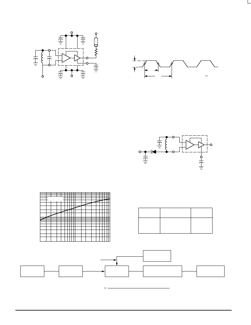
Figure 3. Test Circuit and Waveforms
0.1
μ
F
1200
C
L
10
12
0.1
μ
F
3
*
VCC
**
***
5
VEE
QL
≥
100
* Use high impedance probe (>1.0 Megohm must be used).
** The 1200 ohm resistor and the scope termination impedance constitute
a 25:1 attenuator probe. Coax shall be CT–070–50 or equivalent.
***Bypass only that supply opposite ground.
50%
ta
tb
VP–P
PRF = 1.0MHz
Duty Cycle (Vdc) –
ta
tb
7
8
1
14
0.1
μ
F
0.1
μ
F
***
OPERATING CHARACTERISTICS
Figure 1 illustrates the circuit schematic for the MC1648.
The oscillator incorporates positive feedback by coupling the
base of transistor Q6 to the collector of Q7. An automatic gain
control (AGC) is incorporated to limit the current through the
emitter–coupled pair of transistors (Q7 and Q6) and allow
optimum frequency response of the oscillator.
In order to maintain the high Q of the oscillator, and
provide high spectral purity at the output, transistor Q4 is
used to translate the oscillator signal to the output differential
pair Q2 and Q3. Q2 and Q3, in conjunction with output
transistor Q1, provides a highly buffered output which
produces a square wave. Transistors Q9 and Q11 provide
the bias drive for the oscillator and output buffer. Figure 2
indicates the high spectral purity of the oscillator output
(pin 3).
When operating the oscillator in the voltage controlled
mode (Figure 4), it should be noted that the cathode of the
varactor diode (D) should be biased at least “2” VBE above
VEE (
≈
1.4V for positive supply operation).
When the MC1648 is used with a constant dc voltage to
the varactor diode, the output frequency will vary slightly
because of internal noise. This variation is plotted versus
operating frequency in Figure 5.
Figure 4. The MC1648 Operating in the
Voltage Controlled Mode
0.1
μ
F
L
10
12
C2
3
5
QL
≥
100
Output
Vin
C1
D
1.0–10
10–60
60–100
f
MHz
Figure 5. Noise Deviation Test Circuit and Waveform
100
1
f, OPERATING FREQUENCY (MHz)
VCC = 5 Vdc
f
10
1
10
100
Frequency Deviation
(HP5210A output voltage) (Full Scale Frequency)
1.0Volt
MV2115
MV2115
MV2106
D
100
2.3
0.15
L
μ
H
Oscillator Tank Components
(Circuit of Figure 4)
BW=1.0kHz Frequency
Meter HP5210A or Equiv
Voltmeter RMS
HP3400A or Equiv
MC1648
Frequency (f)
MC1648
Under Test
Attenuator
Product
Detector
Signal Generator
HP608 or Equiv
10mV
20kHz
300mV
20kHz above MC1648 Frequency
相關(guān)PDF資料 |
PDF描述 |
|---|---|
| MC1648FN | Voltage Controlled Oscillator |
| MC1648L | Voltage Controlled Oscillator |
| MC1648P | Voltage Controlled Oscillator |
| MC1650 | Dual A/D Converter |
| MC1650L | Dual A/D Converter |
相關(guān)代理商/技術(shù)參數(shù) |
參數(shù)描述 |
|---|---|
| MC1648FN | 制造商:Rochester Electronics LLC 功能描述:- Bulk |
| MC1648FNR2 | 制造商:Motorola Inc 功能描述: |
| MC1648L | 制造商:Motorola Inc 功能描述: |
| MC1648M | 制造商:Rochester Electronics LLC 功能描述: 制造商:Motorola Inc 功能描述: 制造商:ON Semiconductor 功能描述: 制造商:MOTOROLA 功能描述: |
| MC1648P | 制造商:Panasonic Industrial Company 功能描述:IC |
發(fā)布緊急采購,3分鐘左右您將得到回復(fù)。