- 您現(xiàn)在的位置:買賣IC網(wǎng) > PDF目錄379305 > MC145202F (MOTOROLA INC) Low-Voltage 2.0 GHz PLL Frequency Synthesizer PDF資料下載
參數(shù)資料
| 型號: | MC145202F |
| 廠商: | MOTOROLA INC |
| 元件分類: | XO, clock |
| 英文描述: | Low-Voltage 2.0 GHz PLL Frequency Synthesizer |
| 中文描述: | PLL FREQUENCY SYNTHESIZER, 2000 MHz, PDSO20 |
| 封裝: | SOG-20 |
| 文件頁數(shù): | 11/24頁 |
| 文件大小: | 343K |
| 代理商: | MC145202F |
MC145202
MOTOROLA
11
PDout
Single–Ended Phase/Frequency Detector Output (Pin 6)
This is a three–state current–source/sink output for use as
a loop error signal when combined with an external low–pass
filter. The phase/frequency detector is characterized by a lin-
ear transfer function. The operation of the phase/frequency
detector is described below and is shown in Figure 17.
POL bit (C7) in the C register = low (see Figure 14)
Frequency of fV > fR or Phase of fV Leading fR: current–
sinking pulses from a floating state
Frequency of fV < fR or Phase of fV Lagging fR: current–
sourcing pulses from a floating state
Frequency and Phase of fV = fR: essentially a floating
state; voltage at pin determined by loop filter
POL bit (C7) = high
Frequency of fV > fR or Phase of fV Leading fR: current–
sourcing pulses from a floating state
Frequency of fV < fR or Phase of fV Lagging fR: current–
sinking pulses from a floating state
Frequency and Phase of fV = fR: essentially a floating
state; voltage at pin determined by loop filter
This output can be enabled, disabled, and inverted via the
C register. If desired, PDout can be forced to the high–imped-
ance state by utilization of the disable feature in the C regis-
ter (bit C6). This is a patented feature. Similarly, PDout is
forced to the high–impedance state when the device is put
into standby (STBY bit C4 = high).
The PDout circuit is powered by VPD. The phase detector
gain is controllable by bits C3, C2, and C1: gain (in amps per
radian) = PDout current divided by 2
π
.
φ
R and
φ
V
(Pins 3 and 4)
Double–Ended Phase/Frequency Detector Outputs
These outputs can be combined externally to generate a
loop error signal. Through use of a Motorola patented tech-
nique, the detector’s dead zone has been eliminated. There-
fore, the phase/frequency detector is characterized by a
linear transfer function. The operation of the phase/frequen-
cy detector is described below and is shown in Figure 17.
POL bit (C7) in the C register = low (see Figure 14)
Frequency of fV > fR or Phase of fV Leading fR:
φ
V = nega-
tive pulses,
φ
R = essentially high
Frequency of fV < fR or Phase of fV Lagging fR:
φ
V = essen-
tially high,
φ
R = negative pulses
Frequency and Phase of fV = fR:
φ
V and
φ
R remain essen-
tially high, except for a small minimum time period when
both pulse low in phase
POL bit (C7) = high
Frequency of fV > fR or Phase of fV Leading fR:
φ
R = nega-
tive pulses,
φ
V = essentially high
Frequency of fV < fR or Phase of fV Lagging fR:
φ
R = essen-
tially high,
φ
V = negative pulses
Frequency and Phase of fV = fR:
φ
V and
φ
R remain essen-
tially high, except for a small minimum time period when
both pulse low in phase
These outputs can be enabled, disabled, and inter-
changed via C register bits C6 or C4. This is a patented fea-
ture. Note that when disabled or in standby,
φ
R and
φ
V are
forced to their rest condition (high state).
The
φ
R and
φ
V output signal swing is approximately from
GND to VPD.
LD
Lock Detector Output (Pin 2)
This output is essentially at a high level with narrow low–
going pulses when the loop is locked (fR and fV of the same
phase and frequency). The output pulses low when fV and fR
are out of phase or different frequencies. LD is the logical
ANDing of
φ
R and
φ
V (see Figure 17).
This output can be enabled and disabled via the C register.
This is a patented feature. Upon power up, on–chip initializa-
tion circuitry disables LD to a static low logic level to prevent
a false “l(fā)ock” signal. If unused, LD should be disabled and
left open.
The LD output signal swing is approximately from GND to
VDD.
Rx
External Resistor (Pin 8)
A resistor tied between this pin and GND, in conjunction
with bits in the C register, determines the amount of current
that the PDout pin sinks and sources. When bits C2 and C3
are both set high, the maximum current is obtained at PDout;
see Tables 4 and 5 for other current values. The recom-
mended value for Rx is 3.9 k
. A value of 3.9 k
provides
current at the PDout pin of approximately 1 mA @ VDD = 3 V
and approximately 1.7 mA @ VDD = 5 V in the 100% current
mode. Note that VDD, not VPD, is a factor in determining the
current.
When the
φ
R and
φ
V outputs are used, the Rx pin may be
floated.
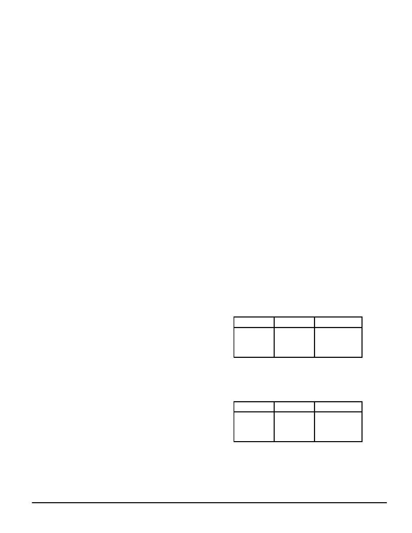
Table 4. PDout Current*, C1 = Low with
OUTPUT A notSelected as “Port”;
Also, Default Mode When OUTPUT A
Selected as “Port”
Bit C3
Bit C2
PDout Current*
70%
80%
90%
100%
0
0
1
1
0
1
0
1
* At the time the data sheet was printed, only the 100%
current mode was guaranteed. The reduced current
modes were for experimentation only.
Table 5. PDout Current*, C1 = High with
OUTPUT A notSelected as “Port”
Bit C3
Bit C2
PDout Current*
25%
50%
75%
100%
0
0
1
1
0
1
0
1
* At the time the data sheet was printed, only the 100%
current mode was guaranteed. The reduced current
modes were for experimentation only.
相關(guān)PDF資料 |
PDF描述 |
|---|---|
| MC14522BCL | Non-inverting Fast Synchronous Buck MOSFET Drivers with Enable 14-HTSSOP |
| MC14522BCP | Presettable 4-Bit Down Counters |
| MC14522BDW | Presettable 4-Bit Down Counters |
| MC14527BCL | BCD Rate Multiplier |
| MC14527BCP | Inverting Fast Synchronous Buck MOSFET Drivers with Enable 14-HTSSOP |
相關(guān)代理商/技術(shù)參數(shù) |
參數(shù)描述 |
|---|---|
| MC14520B | 制造商:Motorola Inc 功能描述: 制造商:ON Semiconductor 功能描述: |
| MC14520BAL | 制造商:Motorola Inc 功能描述:Counter, Up, 4 Bit Binary, 16 Pin, Ceramic, DIP |
| MC14520BCP | 功能描述:計數(shù)器移位寄存器 3-18V Dual BCD Up RoHS:否 制造商:Texas Instruments 計數(shù)器類型: 計數(shù)順序:Serial to Serial/Parallel 電路數(shù)量:1 封裝 / 箱體:SOIC-20 Wide 邏輯系列: 邏輯類型: 輸入線路數(shù)量:1 輸出類型:Open Drain 傳播延遲時間:650 ns 最大工作溫度:+ 125 C 最小工作溫度:- 40 C 封裝:Reel |
| MC14520BCPG | 功能描述:計數(shù)器移位寄存器 3-18V Dual BCD Up RoHS:否 制造商:Texas Instruments 計數(shù)器類型: 計數(shù)順序:Serial to Serial/Parallel 電路數(shù)量:1 封裝 / 箱體:SOIC-20 Wide 邏輯系列: 邏輯類型: 輸入線路數(shù)量:1 輸出類型:Open Drain 傳播延遲時間:650 ns 最大工作溫度:+ 125 C 最小工作溫度:- 40 C 封裝:Reel |
| MC14520BDW | 功能描述:計數(shù)器移位寄存器 3-18V Dual BCD Up RoHS:否 制造商:Texas Instruments 計數(shù)器類型: 計數(shù)順序:Serial to Serial/Parallel 電路數(shù)量:1 封裝 / 箱體:SOIC-20 Wide 邏輯系列: 邏輯類型: 輸入線路數(shù)量:1 輸出類型:Open Drain 傳播延遲時間:650 ns 最大工作溫度:+ 125 C 最小工作溫度:- 40 C 封裝:Reel |
發(fā)布緊急采購,3分鐘左右您將得到回復(fù)。