- 您現(xiàn)在的位置:買(mǎi)賣(mài)IC網(wǎng) > PDF目錄353140 > GM123210GFNNB-01 (Electronic Theatre Controls, Inc.) LCD MODULE SPECIFICATION PDF資料下載
參數(shù)資料
| 型號(hào): | GM123210GFNNB-01 |
| 廠商: | Electronic Theatre Controls, Inc. |
| 英文描述: | LCD MODULE SPECIFICATION |
| 中文描述: | 液晶模組規(guī)格 |
| 文件頁(yè)數(shù): | 4/20頁(yè) |
| 文件大小: | 218K |
| 代理商: | GM123210GFNNB-01 |
第1頁(yè)第2頁(yè)第3頁(yè)當(dāng)前第4頁(yè)第5頁(yè)第6頁(yè)第7頁(yè)第8頁(yè)第9頁(yè)第10頁(yè)第11頁(yè)第12頁(yè)第13頁(yè)第14頁(yè)第15頁(yè)第16頁(yè)第17頁(yè)第18頁(yè)第19頁(yè)第20頁(yè)

Confidential Document
Page:
12 /20
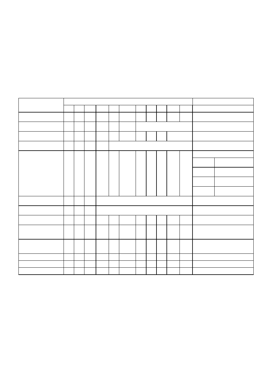
COMMANDS
Summary
Code
Function
Command
A0
RD
WR
D7
D6
D5
D4
D3
D2
D1
D0
Display ON/OFF
0
1
0
1
0
1
0
1
0/1
Turns display on or off.
1 : ON, 0 : OFF
Display start line
0
1
0
1
0
Display start address (0 to 31)
Specifies RAM line corresponding
to top line of display.
Set page address
0
1
0
1
0
1
0
Page (0 to 3)
Sets display RAM page in page
address register.
Set column
(segment) address
0
1
0
Column address (0 to 72)
Sets display RAM column address
in column address register.
Reads the following status:
BUSY
1 : Busy
0 : Ready
ADC
1 : CW output
0 : CCW output
ON/OFF
1 : Display off
0 : Display on
Read status
0
1
Busy ADC ON/OFF Reset
0
RESET
1 : Being reset
0 : Normal
Write display data
1
0
Write data
Writes data from data bus into
display RAM.
Read display data
1
0
1
Read data
Reads data from display RAM
onto data bus.
Select ADC
0
1
0
1
0
1
0
0/1
0 : CW output
1 : CCW output
Static drive
ON/OFF
0
1
0
1
0
1
0
1
0
0/1
Selets static driving operation.
1 : Static drive
0 : Normal driving
Select duty
0
1
0
1
0
1
0
1
0
0/1
Selets LCD duty cycle
1 : 1/32
0 : 1/16
Read – Modify - Write
0
1
0
1
0
Read – modify – write ON
End
0
1
0
1
0
1
0
Read – modify – write OFF
Reset
0
1
0
1
0
1
0
Software reset
相關(guān)PDF資料 |
PDF描述 |
|---|---|
| GM123210NFNNB-01 | LCD MODULE SPECIFICATION |
| GM123210SRNNB-01 | LCD MODULE SPECIFICATION |
| GM123210NMNBB-01 | LCD MODULE SPECIFICATION |
| GM123210GMENB-01 | LCD MODULE SPECIFICATION |
| GM123210SMENB-01 | LCD MODULE SPECIFICATION |
相關(guān)代理商/技術(shù)參數(shù) |
參數(shù)描述 |
|---|---|
| GM123210GFNWB-01 | 制造商:未知廠家 制造商全稱:未知廠家 功能描述:LCD MODULE SPECIFICATION |
| GM123210GFSAB-01 | 制造商:未知廠家 制造商全稱:未知廠家 功能描述:LCD MODULE SPECIFICATION |
| GM123210GFSBB-01 | 制造商:未知廠家 制造商全稱:未知廠家 功能描述:LCD MODULE SPECIFICATION |
| GM123210GFSNB-01 | 制造商:未知廠家 制造商全稱:未知廠家 功能描述:LCD MODULE SPECIFICATION |
| GM123210GFSWB-01 | 制造商:未知廠家 制造商全稱:未知廠家 功能描述:LCD MODULE SPECIFICATION |
發(fā)布緊急采購(gòu),3分鐘左右您將得到回復(fù)。