- 您現(xiàn)在的位置:買賣IC網(wǎng) > PDF目錄379298 > LR8N3 (SUPERTEX INC) High Input Voltage Adjustable 3-Terminal Linear Regulator PDF資料下載
參數(shù)資料
| 型號: | LR8N3 |
| 廠商: | SUPERTEX INC |
| 元件分類: | 基準(zhǔn)電壓源/電流源 |
| 英文描述: | High Input Voltage Adjustable 3-Terminal Linear Regulator |
| 中文描述: | 1.2 V-440 V ADJUSTABLE POSITIVE REGULATOR, PBCY3 |
| 封裝: | TO-92, 3 PIN |
| 文件頁數(shù): | 10/11頁 |
| 文件大小: | 601K |
| 代理商: | LR8N3 |
10
LR8
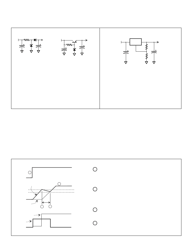
Comparison with Discrete Startup Implementations
The LR8 provides several advantages when compared with discretely implemented start-up circuits.
V
IN
V
OUT
Zener Implementation
V
IN
V
OUT
Transistor Implementation
LR8
V
IN
V
OUT
LR8 Implementation
Advantages
LR8 goes into standby mode after supply has
bootstrapped, drawing no current from high voltage
input
Good regulation
Built-in current limiting
Overtemperature protection
Disadvantages
Continues to draw current from high voltage source after
supply has bootstrapped, resulting in inefficiencies
Bias must be set for minimum input voltage, resulting in
high current drain at high input voltages
Poor regulation
No current limit
No overtemperature protection
In the Zener implementation, requires large power resistor
and Zener
Exceeding LR8’s Current Limit for Startup Applications
The LR8 has a built-in current limit of 10mA minimum. If the current drawn by the PWM controller exceeds this limit, the LR8 may still be
used. To do this, the LR8’s output capacitor supplies a portion of the current until the power supply can bootstrap itself and the LR8 is no
longer needed. The following figure graphically illustrates how this is accomplished.
Most PWM controllers have an undervoltage lockout (UVL) circuit or programmable start/stop voltages. When the voltage supplied to the
PWM controller reaches the turn-on threshold, the controller begins operating and consuming current. If current exceeds the current limit
for the LR8, the voltage at V
OUT
begins to decay. With a large enough capacitor, the supply will bootstrap before voltage decays to the turn-
off threshold.
V
IN
V
OUT
V
HYS
V
BOOT
I
LR8
t
BOOT
10mA
0mA
I
PWM
1
4
2
3
1
Input voltage is applied. The LR8 begins operating (in current
limiting mode since C
OUT
appears as a short). V
OUT
begins to
rise as C
OUT
charges. The PWM controller draws a small
amount of current.
The output voltage of the LR8 reaches the PWM controller’s
turn-on threshold. Controller begins operating, drawing current.
Bootstrap voltage begins climbing while V
OUT
decays since
current drawn by the controller exceeds the LR8’s current limit.
Bootstrap voltage reaches the level of the LR8’s output and
takes over. LR8 current drops to zero.
Power supply reaches steady-state operation.
3
4
2
相關(guān)PDF資料 |
PDF描述 |
|---|---|
| LR8N8 | High Input Voltage Adjustable 3-Terminal Linear Regulator |
| LT1001A | NPN SILICON HIGH FREQUENCY TRANSISTOR |
| LT3014 | 14 pin DIP, 5.0 Volt, HCMOS/TTL, Clock Oscillator |
| LUPA-4000 | 4M Pixel CMOS Image Sensor |
| LUPA-4000-M | 4M Pixel CMOS Image Sensor |
相關(guān)代理商/技術(shù)參數(shù) |
參數(shù)描述 |
|---|---|
| LR8N3 P003 | 制造商:Supertex Inc 功能描述:Standard Regulator Pos 1.2V to 440V 0.01A 3-Pin TO-92 T/R |
| LR8N3-G | 功能描述:線性穩(wěn)壓器 - 標(biāo)準(zhǔn) 450V Adj 3 Termnl RoHS:否 制造商:STMicroelectronics 輸出類型: 極性: 輸出電壓:1.8 V 輸出電流:150 mA 負(fù)載調(diào)節(jié): 最大輸入電壓:5.5 V 線路調(diào)整率: 最大工作溫度:+ 125 C 安裝風(fēng)格:SMD/SMT 封裝 / 箱體:SOT-323-5L |
| LR8N3-G P002 | 制造商:Supertex Inc 功能描述:Linear Regulator IC |
| LR8N3-G P003 | 制造商:Supertex Inc 功能描述:Linear Regulator IC |
| LR8N3-G P005 | 制造商:Supertex Inc 功能描述:Linear Regulator IC |
發(fā)布緊急采購,3分鐘左右您將得到回復(fù)。