- 您現(xiàn)在的位置:買賣IC網(wǎng) > PDF目錄362814 > ISO422 DIFFERENTIAL BUS TRANSCEIVER PDF資料下載
參數(shù)資料
| 型號(hào): | ISO422 |
| 英文描述: | DIFFERENTIAL BUS TRANSCEIVER |
| 中文描述: | 差分總線收發(fā)器 |
| 文件頁數(shù): | 3/8頁 |
| 文件大小: | 251K |
| 代理商: | ISO422 |
3
ISO422
POWER
Supply Voltage—Data Side
Supply Current—Data Side
Supply Current—Data Side
Supply Voltage—Bus Side
Supply Voltage—Bus Side
V
SA
I
SA
I
SA
V
SB
I
SB
4.5
5.5
13
V
Output Unloaded, dc
Output Unloaded, max Rate
10
20
mA
mA
V
mA
mA
4.5
5.5
20
Output Unloaded, dc
Output Unloaded, max Rate
12
20
BUS LIMITS
Input Current
Maximum Differential Input
Maximum Data Rate
±
10
±
5
mA
V
Mbps
2.5
TEMPERATURE RANGE
Operating
Storage
Thermal Resistance
–40
–40
+85
+125
°
C
°
C
θ
JA
75
°
C/W
NOTES: (1) Gull Wing version available Q1’99. (2) All devices receive a 1s test. Failure criterion is > 5 pulses of > 5pC per cycle. (3) Logic inputs are HCT-type
and thresholds are a function of power supply voltage with approximately 100mV hysteresis. (4) Change in magnitude when the input is changed from HIGH to
LOW. (5) The difference between the differential low to high and high to low transition points.
The information provided herein is believed to be reliable; however, BURR-BROWN assumes no responsibility for inaccuracies or omissions. BURR-BROWN
assumes no responsibility for the use of this information, and all use of such information shall be entirely at the user’s own risk. Prices and specifications are subject
to change without notice. No patent rights or licenses to any of the circuits described herein are implied or granted to any third party. BURR-BROWN does not
authorize or warrant any BURR-BROWN product for use in life support devices and/or systems.
SPECIFICATIONS
(CONT)
At T
A
= +25
°
C, and V
S
= +5V, unless otherwise noted.
ISO422P, P-U
(1)
PARAMETER
CONDITIONS
MIN
TYP
MAX
UNITS
PACKAGE DRAWING
NUMBER
(1)
PRODUCT
PACKAGE
ISO422P
ISO422P-U
24-Pin Plastic DIP
24-Pin Gull Wing Surface Mount
243-4
243-5
NOTE: (1) For detailed drawing and dimension table, please see end of data
sheet, or Appendix C of Burr-Brown IC Data Book.
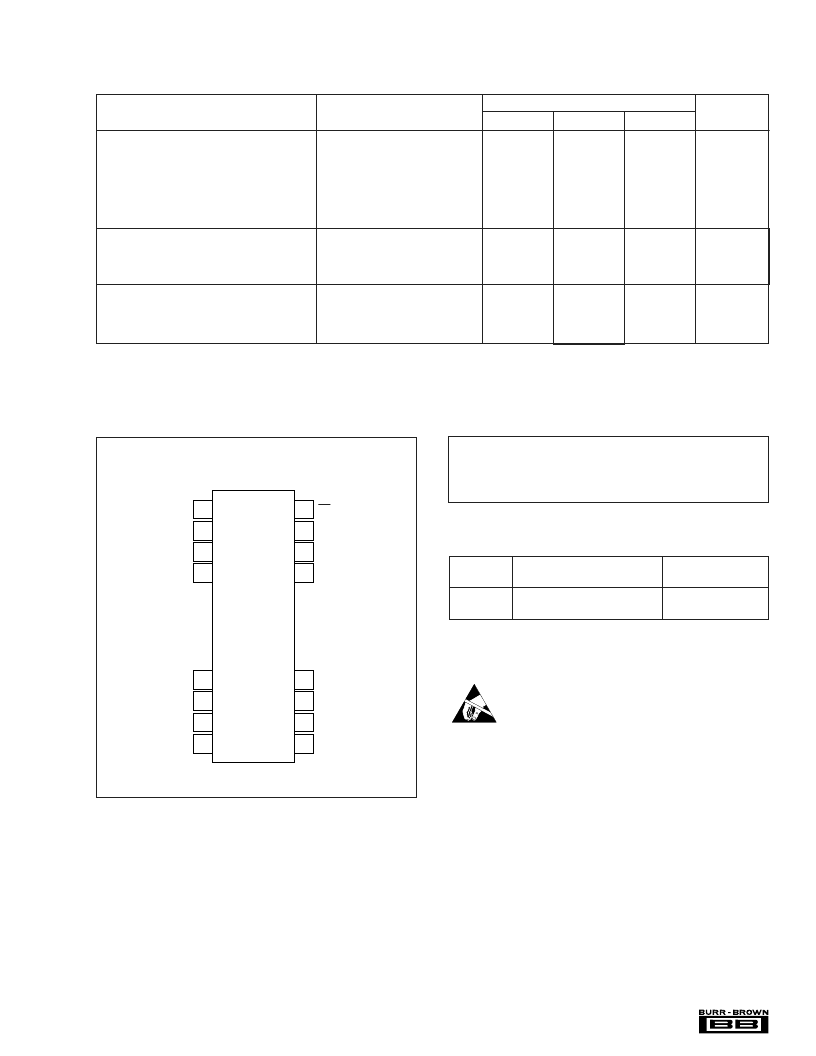
PIN CONFIGURATION
Top View
DIP
ABSOLUTE MAXIMUM RATINGS
Supply Voltage: V
SA
............................................................. –0.5V to +6V
V
............................................................. –0.5V to +6V
Continuous Isolation Voltage .....................................................1500Vrms
Storage Temperature ...................................................... –40
°
C to +125
°
C
Lead Temperature (soldering, 10s) ............................................... +300
°
C
PACKAGE INFORMATION
ELECTROSTATIC
DISCHARGE SENSITIVITY
Electrostatic discharge can cause damage ranging from per-
formance degradation to complete device failure. Burr-
Brown Corporation recommends that all integrated circuits
be handled and stored using appropriate ESD protection
methods.
ESD damage can range from subtle performance degrada-
tion to complete device failure. Precision integrated circuits
may be more susceptible to damage because very small
parametric changes could cause the device not to meet
published specifications.
24
23
22
21
16
15
14
13
1
2
3
4
9
10
11
12
DE
D
NC
V
SA
GND
B
GND
B
Y
Z
RE
R
LBE
GND
A
V
SB
V
SB
A
B
相關(guān)PDF資料 |
PDF描述 |
|---|---|
| ISO422P | DIFFERENTIAL BUS TRANSCEIVER |
| ISO485P | Isolated RS-485 DIFFERENTIAL BUS TRANSCEIVER |
| ISO518P-U | CAT 5 SOLID PVC CABLE STRGHT PIN, 100 MHZ-BLUE |
| ISO518 | Bidirectional ISOLATED DIGITAL COUPLERS |
| ISO518P | Bidirectional ISOLATED DIGITAL COUPLERS |
相關(guān)代理商/技術(shù)參數(shù) |
參數(shù)描述 |
|---|---|
| ISO422P | 制造商:BB 制造商全稱:BB 功能描述:DIFFERENTIAL BUS TRANSCEIVER |
| ISO422P-U | 制造商:BB 制造商全稱:BB 功能描述:DIFFERENTIAL BUS TRANSCEIVER |
| ISO422P-U(1) | 制造商:BB 制造商全稱:BB 功能描述:DIFFERENTIAL BUS TRANSCEIVER |
| ISO485 | 制造商:BB 制造商全稱:BB 功能描述:Isolated RS-485 DIFFERENTIAL BUS TRANSCEIVER |
| ISO485EVM | 功能描述:界面開發(fā)工具 ISO485 Eval Mod RoHS:否 制造商:Bourns 產(chǎn)品:Evaluation Boards 類型:RS-485 工具用于評(píng)估:ADM3485E 接口類型:RS-485 工作電源電壓:3.3 V |
發(fā)布緊急采購,3分鐘左右您將得到回復(fù)。