- 您現(xiàn)在的位置:買賣IC網(wǎng) > PDF目錄362811 > ISC302A Optoelectronic PDF資料下載
參數(shù)資料
| 型號: | ISC302A |
| 英文描述: | Optoelectronic |
| 中文描述: | 光電 |
| 文件頁數(shù): | 8/11頁 |
| 文件大小: | 141K |
| 代理商: | ISC302A |
ISC300
8
excitation current. Four wire measurements avoid this prob-
lem by measuring the voltage generated across the RTD on
a second pair of wires. Very little current flows through the
voltmeter, therefore the lead resistance error contribution is
negligible. Three wire resistance measurements also avoid
lead length resistance errors.
In Figure 8:
(+In)
= –r
1
(I
1
+ I
2
) – r
2
I
1
(–In)
= –r
1
(I
1
+ I
2
) – R
2
I
2
– r
3
I
2
= –r
2
I
2
+ R
S
I
2
+ r
3
I
2
Since r
1
=
r
2
= r
3
(LEADS)
and
I
1
= I
2
V
IN
= R
S
I
2
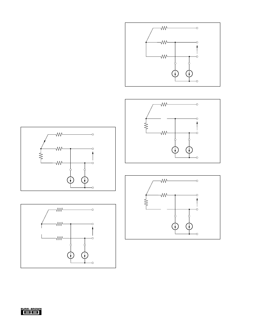
FAULT CONDITIONS
The ISC300 can be configured to detect line or transducer
faults which may occur in a system. Figures 8 to 14 show
how the output of the ISC300 will reflect these various fault
conditions by giving corresponding out of range outputs.
Com 1
+In
–In
0V
–V
ISO
I
2
I
1
R
S
Output < +0.1V
FIGURE 10. R
S
Short Circuit.
Com 1
+In
–In
–V
ISO
–V
ISO
I
2
I
1
R
S
Output < –5.1V
FIGURE 11. +In Open Circuit.
Com 1
+In
–In
+V
ISO
–V
ISO
I
2
I
1
R
S
Output > +5.1V
FIGURE 12. –In Open Circuit.
FIGURE 8. Normal Operation.
Com 1
+In
–In
+V
ISO
–V
ISO
I
2
I
1
R
S
Output > +5.1V
FIGURE 9. R
S
Open Circuit.
Com 1
+In
–In
I
2
R
S
= V
IN
–V
ISO
I
2
I
1
R
S
Output = G V
IN
T
1
T
2
T
3
I
1
+ I
2
(1)
(2)
(1) – (2)
相關PDF資料 |
PDF描述 |
|---|---|
| ISC302B | Optoelectronic |
| ISC302C | Optoelectronic |
| ISC302D | Optoelectronic |
| ISC302E | Optoelectronic |
| ISC302F | Optoelectronic |
相關代理商/技術參數(shù) |
參數(shù)描述 |
|---|---|
| ISC302B | 制造商:未知廠家 制造商全稱:未知廠家 功能描述:Optoelectronic |
| ISC302C | 制造商:未知廠家 制造商全稱:未知廠家 功能描述:Optoelectronic |
| ISC302D | 制造商:未知廠家 制造商全稱:未知廠家 功能描述:Optoelectronic |
| ISC302E | 制造商:未知廠家 制造商全稱:未知廠家 功能描述:Optoelectronic |
| ISC302F | 制造商:未知廠家 制造商全稱:未知廠家 功能描述:Optoelectronic |
發(fā)布緊急采購,3分鐘左右您將得到回復。