- 您現(xiàn)在的位置:買賣IC網(wǎng) > PDF目錄362811 > ISC300 PDF資料下載
參數(shù)資料
| 型號: | ISC300 |
| 文件頁數(shù): | 6/11頁 |
| 文件大小: | 141K |
| 代理商: | ISC300 |
ISC300
6
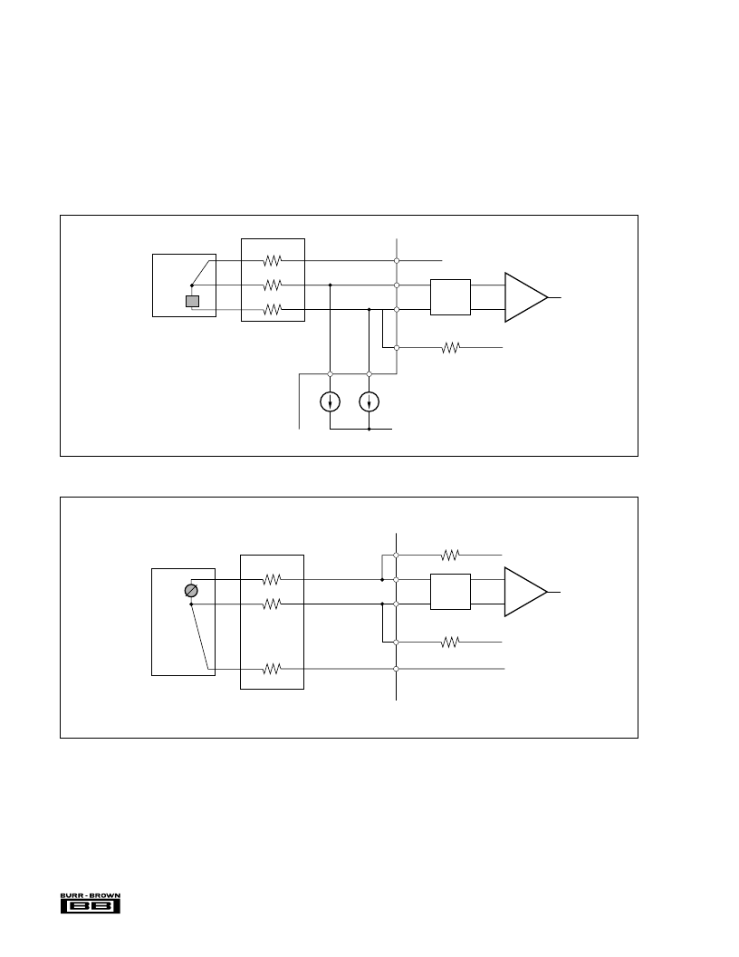
Figure 4 shows the configuration for voltage measurement.
A full scale input range of
±
10V can be accepted by the
ISC300. The two sense lines can be connected to give open
or short circuit detection. An open circuit will result in an
output of < –5.1V and a short circuit will give a < 0.1V
output. See the Applications section under Fault Conditions
for more information.
Figure 7 shows a possible circuit configuration using jump-
ers to select voltage or RTD operation.
ISOLATED SUPPLIES
The two isolated supplies available on the input side are
capable of supplying
±
11.5V min at 5mA. These can be used
to provide power for external front-end circuitry for addi-
tional signal processing. When using the isolated supplies, it
is necessary to decouple them as close to the device as
possible. 10
μ
F tantalum capacitors should be used. This will
also improve the signal-to-noise ratio.
FIGURE 3. Resistance Measurement Configuration.
FIGURE 4. Voltage Measurement Configuration.
+V
ISO
Sense 2
–In
+In
Sense 1
Filter and
MUX
Line Resistance
–10V
to
+10V
–V
ISO
Com 1
PGA
20M
20M
+V
ISO
I
1
I
2
Sense 2
Com 1
– In
+In
Com 1
I
REF1
I
REF2
–V
ISO
Filter and
MUX
Line Resistance
0
to
500
R
S
20M
PGA
相關(guān)PDF資料 |
PDF描述 |
|---|---|
| ISC302A | Optoelectronic |
| ISC302B | Optoelectronic |
| ISC302C | Optoelectronic |
| ISC302D | Optoelectronic |
| ISC302E | Optoelectronic |
相關(guān)代理商/技術(shù)參數(shù) |
參數(shù)描述 |
|---|---|
| ISC302A | 制造商:未知廠家 制造商全稱:未知廠家 功能描述:Optoelectronic |
| ISC302B | 制造商:未知廠家 制造商全稱:未知廠家 功能描述:Optoelectronic |
| ISC302C | 制造商:未知廠家 制造商全稱:未知廠家 功能描述:Optoelectronic |
| ISC302D | 制造商:未知廠家 制造商全稱:未知廠家 功能描述:Optoelectronic |
| ISC302E | 制造商:未知廠家 制造商全稱:未知廠家 功能描述:Optoelectronic |
發(fā)布緊急采購,3分鐘左右您將得到回復(fù)。