- 您現(xiàn)在的位置:買賣IC網(wǎng) > PDF目錄384457 > HV9903 (Supertex, Inc.) White LED Driver PDF資料下載
參數(shù)資料
| 型號: | HV9903 |
| 廠商: | Supertex, Inc. |
| 元件分類: | LED驅(qū)動器 |
| 英文描述: | White LED Driver |
| 中文描述: | 白光LED驅(qū)動器 |
| 文件頁數(shù): | 4/12頁 |
| 文件大小: | 326K |
| 代理商: | HV9903 |
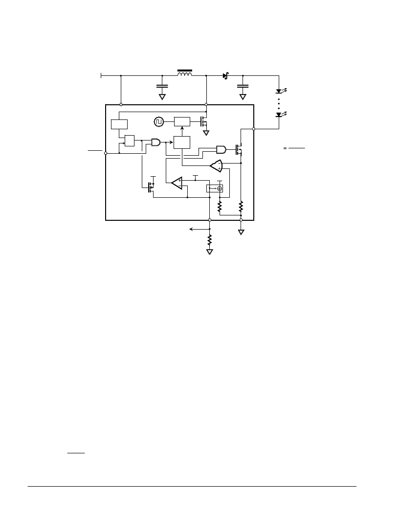
Functional Block Diagram
SET
LED
I
R
V
5
22
HV9903
L
D
C
OUT
C
DD
V
DD
SHDN
OVP
PWM
Soft
Start
R
S
Q
1.2MHz
V
DD
SW
GND
LED
V
DD
100mV
R
SET
Fault
75R
R
enable
1:3
V
DD
mirror
aerr
R
SET
Note: This drawing is a generalized representation of the HV9903. Actual internal circuitry may differ.
Operation
The HV9903 operates as a boost converter that
regulates output current rather than output voltage.
To maintain constant output current, LED current is
monitored via the LED pin and the boost converter’s
PWM duty cycle is adjusted accordingly to maintain
the desired current level. LED current is controlled
100% via the PWM boost converter – the MOSFET
connected to the LED pin is fully turned on during
normal operation and is not regulated to maintain
constant LED current. This minimizes voltage drop at
the LED pin, maximizing overall efficiency.
LED current is set by the value of the resistor
connected to the R
SET
pin. The voltage at the R
SET
pin
is maintained at 100mV and the resulting current
through the R
SET
resistor is used as a reference for
LED current control. LED current is regulated at 225
times R
SET
current.
SET
LED
R
I
V
5
22
=
Current through the R
SET
pin is monitored. If it falls
below 1.5
μ
A, both the PWM boost converter switch
and LED switch are turned off. Soft-start is not reset
and the IC does not go into low power standby. Such
a condition can occur two ways: 1) if R
SET
is greater
than about 66k
, or 2) an external voltage greater
than 100mV is applied to the R
SET
pin. Internal
blocking prevents reverse current flow into the R
SET
pin if the externally applied voltage exceeds 100mV.
However, applied voltage must not exceed V
DD
.
The control loop is designed for discontinuous mode
operation. That is, inductor current is allowed to
return to zero between PWM conversion cycles. To
assure discontinuous mode operation, the inductor
value must be below a certain value for given
conditions of supply voltage and LED string voltage
drop. The Inductor Selection section provides further
information.
The PWM boost converter is a current mode controller
operating at an internally fixed 1.2MHz.
A soft-start circuit minimizes inrush current when
power is initially applied or the device is enabled via
the SHDN input. Inrush current is typically limited to
130% of steady-state current. Although the soft-start
period is short (~1ms), it means that if using SHDN for
PWM dimming, the PWM dimming signal should be
HV9903
HV9903
4
相關(guān)PDF資料 |
PDF描述 |
|---|---|
| HV9904 | HV9904 Multi Converter Controller |
| HV9904LG | HV9904 Multi Converter Controller |
| HV9904P | HV9904 Multi Converter Controller |
| HV9904X | HV9904 Multi Converter Controller |
| HV9906 | Simple Off-Line/PFC & >9V DC/DC Switcher |
相關(guān)代理商/技術(shù)參數(shù) |
參數(shù)描述 |
|---|---|
| HV9903DB1 | 制造商:Supertex Inc 功能描述: |
| HV9903K6 | 功能描述:LED照明驅(qū)動器 White LED Drvr RoHS:否 制造商:STMicroelectronics 輸入電壓:11.5 V to 23 V 工作頻率: 最大電源電流:1.7 mA 輸出電流: 最大工作溫度: 安裝風格:SMD/SMT 封裝 / 箱體:SO-16N |
| HV9903K6-G | 功能描述:LED照明驅(qū)動器 White LED Drvr RoHS:否 制造商:STMicroelectronics 輸入電壓:11.5 V to 23 V 工作頻率: 最大電源電流:1.7 mA 輸出電流: 最大工作溫度: 安裝風格:SMD/SMT 封裝 / 箱體:SO-16N |
| HV9904 | 制造商:SUPERTEX 制造商全稱:SUPERTEX 功能描述:HV9904 Multi Converter Controller |
| HV9904LG | 功能描述:功率驅(qū)動器IC HVCMOS D2 RoHS:否 制造商:Micrel 產(chǎn)品:MOSFET Gate Drivers 類型:Low Cost High or Low Side MOSFET Driver 上升時間: 下降時間: 電源電壓-最大:30 V 電源電壓-最小:2.75 V 電源電流: 最大功率耗散: 最大工作溫度:+ 85 C 安裝風格:SMD/SMT 封裝 / 箱體:SOIC-8 封裝:Tube |
發(fā)布緊急采購,3分鐘左右您將得到回復。